Table of Contents
Advertisement
Quick Links
Advertisement
Table of Contents

Subscribe to Our Youtube Channel
Related Manuals for Induction Solutions Boogie Box NPC-1006

Summary of Contents for Induction Solutions Boogie Box NPC-1006
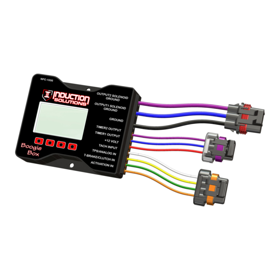
- Page 1 NPC-1006 Progressive Controller User Manual Boogie Box Important—if using the Throttle Position Input for activation refer to Wiring Diagram #3. Induction Solutions 16121 Flight Path Dr Brooksville, FL 34604 352-593-5900 Phone 352-593-5901 Fax email: info@inductionsolutions.com...
- Page 2 What is Included with the NPC‐1006 kit. NPC‐1006 Nitrous Controller. Wiring Harness with sealed automo ve connectors. Installa on hardware kit. User Manual Important Informa on ‐ When using a conven onal style igni on coil (Not Coil on Plug) you must use Sta c Suppression Igni on Wires with this Controller. on ‐ Do NOT submerge Controller in liquid or directly wash unit with liquid of any type! (Do NOT spray when washing vehicle!) It is the responsibility of the purchaser to follow all guidelines and safety procedures supplied with this product and any other manufactures product used with this product.
-
Page 3: Table Of Contents
Contents User Interface Main Screen and User Interface Overview Page 5 Drop Down Menu Overview Page 6 Slider Bar, Value Adjust Overview Page 6 Solenoid Output Graph Setup Overview Page 7 Using the Integrated Help Page 8 Viewing Help Text Page 8 ... - Page 4 Timer Menu Timer1 Setup Page 16 Timer1 Sync Page 16 Ac va on input Enable Page 16 Trans Brake input Enable Page 17 Delay Timer Enable Page 17 Timer On Delay Page 17 Timer Off Delay Page 17 RPM Control Enable Page 17 On RPM Page 18...
-
Page 5: Main Screen And User Interface Overview
Main Screen and User Interface Overview Output2 Percent Output1 Percent Selected Setup Main Timer Activation Input TPS Percent Tran Brake Input Output1 Button Output2 Button Timer Button Setup Button Output1 Setup Output2 Setup Timer Setup Global options Output1 Percent—Readout that displays current Output1 duty cycle percentage. Output2 Percent—Readout that displays current Output2 duty cycle percentage. -
Page 6: Drop Down Menu Overview
Drop Down Menu Naviga on Menu Title Current Selection Scroll Position Back Button Up Button Down Button Enter Button Exit Menu Selection Up Selection Down Menu Item Select Back Bu on—use this bu on to go back or exit to previous screen. Up Bu on—use this bu on to move the highlighted menu item up. Down Bu on—use this bu on to move the highlighted menu item down. -
Page 7: Solenoid Output Graph Setup Overview
Solenoid Output Graph View Naviga on Ramp Position Select Ramp Exit Graph View Field to Edit Value Adjust Value Adjust Select ramp posi on to edit. 1—make sure SELECT bu on reads SELECT, if not press the bu on un l it reads SELECT. 2—use the le and right arrow keys to move the cursor between the ramp posi ons. The ramp posi on readout will change and display the current ramp posi on. -
Page 8: Using The Integrated Help
Using the Integrated Help Yes Button No Button Off Button View Help Text Do NOT View Help Turn OFF Help Yes Bu on—use this bu on to view help text associated with the current menu selec on. No Bu on—use this bu on to decline viewing help text. Off Bu on—use this bu on to turn Off... -
Page 9: Current Setup
Setup Menu—Current Setup There are 3 Data Setups available. The current se ngs will be saved when selec ng a New Data Setup from the list. This way mul ple User Setups can be stored and recalled at a later me. Example ‐ you have a Setup that is working well, you decide that you would like to try a few different se ngs. You could then Select and Copy current Setup Data to a New Setup and make changes without loosing the original setup. -
Page 10: Tach Pulse Count
Setup Menu—Tach Pulse Count Tach Input Pulse Per Revolu on ‐ this se ng determines the number of Tach Pulses per revolu on of the cranksha . Example ‐ if the Tach Signal input is connected to a common V8 engine mul ‐spark igni on controller a se ng of 4 Pulse per Revolu on would be used. -
Page 11: Setup Menu
Setup Menu—Minimum RPM Minimum RPM ‐ this se ng controls the minimum engine RPM that must be achieved before Outputs will turn On. A se ng of 0 will disable the Minimum RPM func on and the Maximum RPM se ng will be used to turn off the Outputs if the engine RPM exceeds the se ng. -
Page 12: Program Tps Voltage
Setup Menu—TPS Input Setup—Program TPS Voltage The TPS Input Closed and Wide Open Thro le can be set using Live data from the TPS Input or these values can be set manually. With the key on but the engine off, with your foot off the thro le press the SET MIN bu on, apply full thro le and press the SET MAX bu on. -
Page 13: Help Text Enable/Disable
Setup Menu—Help Text Enable/Disable This se ng turns the help text on or off. 1—Press the SETUP bu on from the main screen. 2—Highlight the Help is (ON/OFF) menu selec on and press the ENTER bu on. 3—Choose YES or NO to enable or disable the op on. 4—Press the BACK bu on to return to the main screen. -
Page 14: Output1 Menu
Output1 Menu—Output1 Ramp Setup—Number of Ramps This se ng determines the total number of progressive ramps available for this output channel. The number of ramps is adjustable from 1 to 5. Note—each output can have a different number of ramps (set points). 1—Highlight the Number of Ramps menu selec on and press the ENTER bu on. (If Help is on choose op on) 2—Adjust the value as desired. -
Page 15: Output1 Delay
Output1 Menu—Output1 Delay This se ng controls the delay me in seconds before the output starts a er ac va on. 1—Highlight the Output1 Delay menu selec on and press the ENTER bu on. (If Help is on choose op on) 2—Adjust the value as desired. (See “Slider Bar, Value Adjust Overview”) 3—Press the BACK bu on to return to the main screen. - Page 16 Timer Menu—Timer1 Setup Stage1 Timer, Timing Retard Control ‐ this se ng configures the Stage1 Timer, +12V output to be On whenever Output1 is On (Solenoids func oning). If this se ng is Off then the Timer1 output can be configured by selec ng which control parameters are used to turn On the mer output.
- Page 17 Timer Menu—Timer1 Setup—Trans Brake Enable When this se ng is On the Timer1 output will be on when the Trans Brake Input has +12V applied. 1—Highlight the Tbrake Enable (ON/OFF) menu selec on and press the ENTER bu on. (If Help is on choose op on) 2—Choose YES or NO to enable or disable the op on.
- Page 18 Timer Menu—Timer1 Setup—On RPM Engine RPM On, Off ‐ these se ngs control the Timer output based on Engine RPM. If the On se ng is 0 the output will be On un l the engine rpm exceeds the OFF RPM se ng. If the OFF RPM se ng is 0 the output will remain Off...
- Page 19 Wiring Diagram #1—(Common Plate System) current draw less than 30amps combined. Wiring Diagram #2—(Direct Port System) current draw less than 35amps combined. ...
- Page 20 Wiring Diagram #3—(Direct Port High Amp) current draw more than 35amps combined. Wiring Diagram #4—(2‐Stage Direct Port High Amp) current draw more than 35amps combined. ...
- Page 21 Transmission Brake/Clutch Input Wiring Important Informa on—when then Trans‐Brake/Clutch input is ON the Ac va on input will be ignored un l the transmission brake or clutch is released. This keeps the nitrous OFF when the Trans‐Brake/Clutch input is ON and the thro le is wide open. RPM/Tachometer Input Wiring ...
- Page 22 Timer1 +12 Volt Output Wiring This output provides +12 volt at 1 amp maximum, there is an internal 1k ohm resistor to ground so the output is not floa ng when in the off state. If your igni on and/or igni on ming controller is ac vated by a +12 volt signal the 20ga Blue Timer1 Output wire can be connected directly to retard ac va on.
Need help?
Do you have a question about the Boogie Box NPC-1006 and is the answer not in the manual?
Questions and answers