
Subscribe to Our Youtube Channel
Related Manuals for Induction Solutions NPC-2006

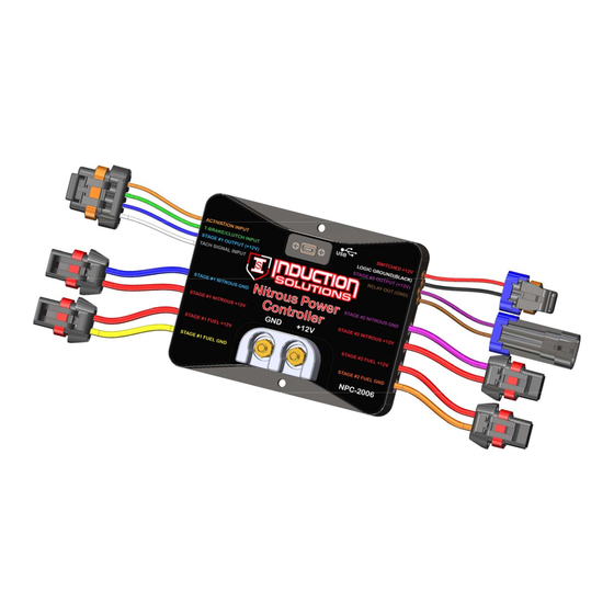
Summary of Contents for Induction Solutions NPC-2006
- Page 1 NPC-2006 Nitrous Power Controller Induction Solutions 16121 Flight Path Dr Brooksville, FL 34604 352-593-5900 Phone 352-593-5901 Fax email: info@inductionsolutions.com...
- Page 2 What is Included with the NPC‐2006 kit. NPC‐2006 Nitrous Controller. Wiring Harness with sealed automo ve connectors. 8ga heavy duty solenoid power supply wires. High Amperage Relay. Installa on hardware kit. USB flash drive with PC so ware and a pdf file of the user manual. User Manual Important Informa on ‐...
-
Page 3: Table Of Contents
Contents So ware Installa on System Requirements Page 4 Installa on Steps Page 4 Using the So ware General Overview Page 7 File Menu Page 8 Controller Menu Page 8 Preferences Menu Page 9 Data Menu Page 9 Help Menu Page 9 Stage1 Tab Setup... -
Page 4: System Requirements
System Requirements Opera ng system Windows XP Home or Professional with Service Pack 3 installed. Informa on—if the text is not forma ed or sized correctly with Windows XP opera ng system follow the instruc ons below to adjust the display dots per inch (dpi) se ng. For Windows XP the screen dpi se ng must be set to default or 96 dpi. - Page 5 Le click on the Induc on Solu ons Drive. Double click on NPC‐2006_Setup...
- Page 6 Click on the “Next” bu on and follow the installa on wizard prompts as needed. Important—Please allow the installa on wizard to install the so ware in the default loca on when prompted. You may be prompted to allow installa on from an unknown publisher, click on “Yes” to con nue with installa on. Allow the installa on program to complete.
-
Page 7: General Overview
General Overview Toolbar menu Hover mouse cursor over icon for informa on. Tabbed naviga on bu ons Menu bar Click on the “I” bu ons for help. Progress bar– this pro‐ Firmware version—this indi‐ cates the current firmware vides visual feedback for installed in the controller. -
Page 8: File Menu
File Menu Open File—open setup file that has been previously saved to the computer. Save File—save current setup file to computer. This op on saves the current setup data from the Nitrous Power Controller so ware. It does not save the setup data from the controller to the computer. Save As—save current setup file to computer with the op on to save as a copy with a different name. -
Page 9: Preferences Menu
Preferences Menu Load Last File on Startup—if the op on is selected (checkmark present) the most recent setup file will be auto‐ ma cally opened when the Nitrous Power Controller so ware is launched. Note—if the file does not exist or has been moved to a new loca on the default setup will opened. -
Page 10: Stage1 Tab-Setup
Stage1 Tab—Setup Stage1 Delay Timer ‐ this se ng sets the delay me in seconds before Stage1 starts a er Ac va on. Valid range ‐ 0.000 to 10.000 in .001 second increments. Note—If the RPM window feature is enabled and the engine is not running the solenoids can be dry fired for tes ng. -
Page 11: Nitrous
Stage1 Tab—Nitrous Graph Edit point Graph Control Edi ng Le click on a data point to enable edi ng for that data point. Le click and drag to adjust the value of the selected data point. Click on the graph or another data point to disable the current edit point. Double le click on a data point to set an anchor point, once the anchor point is set le click on another data point and when the value is changed the graph will auto fill between the anchor point and the current edit point. - Page 12 Important —if the “All Solenoids use Stage1 Nitrous pulse frequency.” op on is checked this se ng will control all nitrous and fuel solenoid frequency (hertz). See Stage1 Setup and Stage2 Setup for more informa on. The solenoid pulse frequency (or also known as Hertz) is how many mes the solenoids open and close when not at 0 or 100 percent opera on.
-
Page 13: Fuel
Stage1 Tab—Fuel Graph Stage1 Nitrous ramp Edit point Anchor point Graph Control Edi ng Le click on a data point to enable edi ng for that data point. Le click and drag to adjust the value of the selected data point. - Page 14 Important —the “All Solenoids use Stage1 Nitrous pulse frequency.” op on must be un‐checked (off) When this feature is enable the Stage2 solenoid frequency (hertz) can be adjusted independently of the Stage1 frequency (hertz). The solenoid pulse frequency (or also known as Hertz) is how many mes the solenoids open and close when not at 0 or 100 percent opera on.
-
Page 15: Setup
Stage2 Tab—Setup Enable Stage2—this se ng allows the en re Stage2 system to be turned off/on as desired. Important—when Stage is off the Stage2 Timer output will be disabled as well as any Stage2 se ngs for Timer1 Output and the Relay output. -
Page 16: Nitrous
Stage2 Tab—Nitrous Graph Stage2 Fuel ramp Edit point Anchor point Graph Control Edi ng Le click on a data point to enable edi ng for that data point. Le click and drag to adjust the value of the selected data point. - Page 17 Important —the “All Solenoids use Stage1 Nitrous pulse frequency.” op on must be un‐checked (off) and the “Stage1 Ni‐ trous and Fuel Solenoids independent frequency.” must be selected for the feature to enabled. When this feature is ena‐ ble the fuel solenoid frequency (hertz) can be adjusted independently of the nitrous frequency (hertz). The solenoid pulse frequency (or also known as Hertz) is how many mes the solenoids open and close when not at 0 or 100 percent opera on.
-
Page 18: Fuel
Stage2 Tab—Fuel Graph Graph Control Edi ng Le click on a data point to enable edi ng for that data point. Le click and drag to adjust the value of the selected data point. Click on the graph or another data point to disable the current edit point. Double le click on a data point to set an anchor point, once the anchor point is set le click on another data point and when the value is changed the graph will auto fill between the anchor point and the current edit point. - Page 19 Important —the “All Solenoids use Stage1 Nitrous pulse frequency.” op on must be un‐checked (off) and the “Stage2 Ni‐ trous and Fuel Solenoids independent frequency.” must be selected for the feature to enabled. When this feature is ena‐ ble the fuel solenoid frequency (hertz) can be adjusted independently of the nitrous frequency (hertz). The solenoid pulse frequency (or also known as Hertz) is how many mes the solenoids open and close when not at 0 or 100 percent opera on.
-
Page 20: Timer Stage1 Tab
Timer Stage1 Tab Stage1 Timer, Timing Retard Control ‐ this se ng configures the Stage1 Timer, +12V output to be On whenever Stage1 Nitrous is On (Solenoids func oning). Check to enable. If this se ng is Off then the Timer1 output can be configured by selec ng which control parameters are used to turn On the output. When more than one control parameter has been selected all must meet the condi ons as configured before the output will func on. -
Page 21: Timer Stage2 Tab
Timer Stage2 Tab Stage2 Timer, Timing Retard Control ‐ this se ng configures the Stage2 Timer, +12V output to be On whenever Stage2 Nitrous is On (Solenoids func oning). Check to enable. If this se ng is Off then the Timer2 output can be configured by selec ng which control parameters are used to turn On the output. When more than one control parameter has been selected all must meet the condi ons as configured before the output will func on. -
Page 22: Relay Output Tab
Relay Output Tab Relay Output Configura on ‐ check to enable which control parameters are used to deter‐ mine when the Relay output will be On. This output provides a Ground when it is On. Maximum current draw is 1 amp. Delay Timer ‐... -
Page 23: Configura On Tab
Configura on Tab Main Timer ‐ This se ng controls the Main Timer period. This controls the total me elapsed before a System Timeout occurs. This limits the total amount of me the solenoids can be On if the Ac va on signal is never removed. Once the Main Timer has med out the Ac va on signal must be removed before the controller may be ac vated again. -
Page 24: Data Tab - Data Setup
Data Tab – Data Setup Data Log Ac va on ‐ these se ngs determine when the controller begins recording data. If more than one op on is selected ALL condi ons must be met before a new data log will start. -
Page 25: Wiring Diagram
Wiring Diagram This relay is included with the kit. +12V Input Required... -
Page 26: Transmission Brake/Clutch Input Wiring
Transmission Brake/Clutch Input Wiring Important Informa on—when then Trans‐Brake/Clutch input is ON the Ac va on input will be ignored un l the transmission brake or clutch is released. This keeps the nitrous OFF when the Trans‐Brake/Clutch input is ON and the thro le is wide open. RPM/Tachometer Input Wiring Typical a ermarket CDI igni on tachometer wiring. -
Page 27: Stage1 +12 Volt Timer Output Wiring
Stage1 +12 Volt Timer Output Wiring This output provides +12 volt at 1 amp maximum, there is an internal 1k ohm resistor to ground so the output is not floa ng when in the off state. If your igni on and/or igni on ming controller is ac vated by a +12 volt signal the 20ga Blue Stage1 Output wire can be connected directly to retard ac va on. -
Page 28: Controller Firmware Update
Controller Firmware Update The NPC‐2006 controller can be updated using the USB interface. An update installs new firmware (so ware) into the controller. The firmware update file should be copied to C:\My Documents\Nitrous Power Controller\Firmware Updates so it can be located easily during the update process. - Page 29 5—please be pa ent while the controller update con nues. 6—when prompted select the new firmware file to load and click on “Open” 7—please be pa ent while the controller update con nues. 8—when the firmware update process is complete click on “Ok”.
-
Page 30: Appendix A-Se Ng Up The Controller For A Run
Appendix A—Se ng up the controller for a run 1—Crea ng and saving a user setup file to the PC. A—Launch the Nitrous Power Controller so ware. Note—if you have the “Preferences‐>Load Last File on Startup” op on checked the setup file that was open the last me the so ware was used will automa cally be opened when you launch the so ware. -
Page 31: Appendix B-Typical Procedure When Making A Run
Appendix B—Typical procedure when making a run A—Edit and upload a setup to the controller. Important—it is the responsibility of the user to create a proper setup for their applica on! B—Perform any usual pre‐race prepara ons, clean res, purge nitrous system, etc. C—Make sure nitrous arming switch is on. -
Page 32: Appendix C-Retrieving Data Log A Er A Run
Appendix C—Retrieving data log a er a run 1—Download data log a er a run. A—Launch the Nitrous Power Controller so ware. B—Connect the USB cable to the controller and the PC. Make sure the controller is powered up. Note—you can look at the status bar at the bo om of the so ware window to see if the controller is connected. C—Download the data log to the controller using “Controller‐>Download Data Log from Controller”...
Need help?
Do you have a question about the NPC-2006 and is the answer not in the manual?
Questions and answers
Wiring diagram to msd 3 step retard
The wiring diagram for connecting the Induction Solutions NPC-2006 to an MSD 3-step retard involves using the Stage1 +12 Volt Timer Output. The 20-gauge blue Stage1 Output wire provides a +12V signal at up to 1 amp and includes an internal 1k ohm resistor to ground. This wire can be connected directly to the MSD 3-step retard activation input if it is triggered by a +12V signal. If the load exceeds 1 amp, a relay must be used. Always perform a dry test (engine running, solenoids unplugged) to confirm proper timing retard before using nitrous.
This answer is automatically generated