Table of Contents
Advertisement
Advertisement
Table of Contents

Related Manuals for jotron TR-810


Summary of Contents for jotron TR-810
- Page 1 OPERATOR AND INSTALLATION MANUAL TR-810 www.jotron.com...
- Page 2 FCC part 15 and part 87 Health and Safety: IEC 60945 ed.4 and EN60950-1 Radio specifications: EN 300 676-1 v.1.4.1 For an updated list of approvals and statements of conformity, these are available on www.jotron.com 84417_O&I_TR-810_G Introduction Page 1-2...
- Page 3 List of abbreviations and definitions BITE Built In Test Equipment Bits Per Second. Digital Signal Processor ETSI European Telecommunication Standardisation Institute ICAO International Civil Aviation Organization International Electro-technical Commission. Operators Control Panel (In this manual: Front module) Power Amplifier Power Supply Unit. Separate unit to power the equipment. Push To Talk Radio Frequency SIGNAL- TO-NOISE RATIO...
- Page 4 Amendment Record INIT DATE PAGE(S) VERSION REASON FOR CHANGE Total: 33 84417_OM_TR-810_A New manual 09.05.08 1-1, 2-1 84417_OM_TR-810_B Change in Tables 08.07.08 84417_O&I_TR-810_C Operation and 14.10.08 Total:32 Installation manual 1-1, 1-2,4-6, 84417_O&I_TR-810_D Added Man-Pack 04.03.10 5-7, 7-1 Change in table 5.7-1 07.12.10 5.4/7.1- 84417_O&I_TR-810_E...
- Page 5 The information in this book has been carefully checked and is believed to be accurate. However, no responsibility is assumed for inaccuracies. Jotron AS reserves the right to make changes without further notice to any products or modules described herein to improve reliability, function or design. Jotron AS does not assume any liability arising out of the application or use of the described product.
- Page 6 Do not force plugs in place, as this may damage the pins in the plugs. Do not pull the cables when removing connectors from the TR-810, take instead a firm grip around the connector, press in the locking pin and pull.
- Page 7 WARNING STATEMENT This device complies with part 15 of the FCC Rules. Operation is subject to the following two conditions: (1) This device may not cause harmful interference, and (2) this device must accept any interference received, including interference that may cause undesired operation.
-
Page 8: Table Of Contents
INTRODUCTION ........................1-10 ................... 1-10 ODELS COVERED BY THIS MANUAL .................... 1-11 AYOUT OF THE TRANSCEIVER ........................1-11 PPLICATIONS TECHNICAL SPECIFICATIONS.................... 2-1 , TR-810 ..................2-1 ENERAL SPECIFICATION FUNCTIONAL DESCRIPTION ....................3-1 ....................3-1 RONT MODULE CONTROLS 3.1.1 Display ..........................3-1 3.1.2 Scroll/Select switch and Navigation buttons A, B and C .......... - Page 9 EAR CONNECTION 7.3.1 Dc input .......................... 7-5 7.3.2 Radio connector ......................7-5 7.3.3 Ext connector ........................7-5 7.3.4 Dc output ........................7-5 TR-810 B ....................7-6 ATTERY NDICATOR TR-810 M ................7-7 EASURES OF ORTABLE TR-810 M ............... 7-9...
-
Page 10: Introduction
See Table 1.1-2 10 Watt 118-137 MHz TR-810 Transceiver, Offshore (OF) 86420 See Table 1.1-2 10 Watt 118-137 MHz TR-810 Transceiver, Last Resort (LR) 86418 See Table 1.1-2 10 Watt 118-137 MHz TR-810 Transceiver, Man Portable (MP) 86416 See Table 1.1-2... -
Page 11: Layout Of The Transceiver
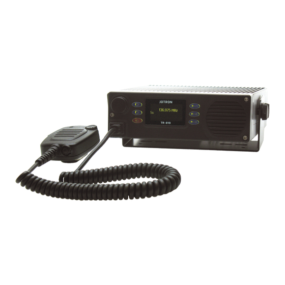
Figure 1.2-1, Transceiver, TR-810 with microphone 1.3 Applications The TR-810 AM transceiver can be used for ground to air voice and can be operated in the following modes: • Locally, mounted into a vehicle, with a microphone connected to the front module connector or to the transceiver unit micII connector. -
Page 12: Technical Specifications
Technical SPECIFICATIONS 2.1 General specification, TR-810 TR-810 Radio performance EN 300 676 v.1.3.1 Temperature range -20°C to +55°C (operating) -40°C to +70°C (storage) Humidity 90% @+40°C (non condensing) Shock & Vibration Transport: EN 300 019-2-2 Shock & Vibration Ground Vehicle installations: EN 300 019-2-5 Shock &... -
Page 13: Functional Description
Functional description 3.1 Front module controls Scroll Display /Select Navigation Preset button (A) Channel Navigation Internal button (C) loadspeaker Mic/Headse Navigation t connector button (B) Figure 3.1-1, Front module controls 3.1.1 Display The display shows the most important operational parameters, selected channel and frequency. -
Page 14: Scroll/Select Switch And Navigation Buttons A, B And C
3.1.2 Scroll/Select switch and Navigation buttons A, B and C The Scroll/Select switch together with the navigation buttons, A, B and C, are used to navigate through the menus. The Scroll/Select switch has three actions: It can be turned clockwise, anti-clockwise, or momentarily pressed. In general the use of the navigation buttons are: A has two functions: Select Channel or One step back... -
Page 15: Preset Channel Buttons
The Red wire is the positive connection and Black wire is the negative. A thin Green wire is together with the DC input wires. This wire can be connected to + voltage through the ignition key, to automatically turn the TR-810 off when the ignition is turned off. -
Page 16: I/O Connector (Rj45)
To tape recorder etc. 600Ω unbalanced LOW POWER Grounding this pin will force the transmitter to 1W power (Gas alarm) BATT.COM Communication between B-872 & TR-810 MUTE Used to mute external equipment. Triggered by squelch +12VDC +12 VDC to external equipment (100mA) Common ground Table 3.2.3-1, I/O connector, pin out... -
Page 17: Installation
Accessory list Table 4.3-1, Inspection procedures On receipt of the radio unit, remove all transit packaging and check that there is no damage to the equipment. If damage is evident, contact Jotron AS immediately and retain the original transit packaging. 84417_O&I_TR-810_G ... -
Page 18: Split Installation Parts
4.4.1 Split installation parts Figure 4.4.1-1 shows some extra parts used for split installation. The TR-810 can be mounted as a Mobile radio, Desk top or flush mounted into a horizontal or vertical area. The front module can be mounted separately away from the transceiver unit using an extension cable and a mounting plate or a bracket. -
Page 19: Measures Of Tr-810
4.4.2 Measures of TR-810 Figure 4.4.2-1, Measures of TR-810 84417_O&I_TR-810_G Installation Page 4-3... -
Page 20: Desktop Mounting
4.4.3 Desktop Mounting Figure 4.4.3-1, Standard desktop mounting Figure 4.4.3-2, Split desktop mounting 84417_O&I_TR-810_G Installation Page 4-4... -
Page 21: Flush Mounting
4.4.4 Flush mounting Figure 4.4.4-1, Standard flush mounting Hole in desk or wall for the connection cable between front module and transceiver unit Figure 4.4.4-2, Split flush mounting 84417_O&I_TR-810_G Installation Page 4-5... -
Page 22: Antenna Connectors
4.5 Antenna connectors The antenna should be of good quality with regards to gain and VSWR to obtain maximum performance. Make sure that the VSWR on the antenna is low, and that the cable from the transmitter to the antenna is of good quality to avoid mismatch and unnecessary losses. A cable loss of 1 dB is the same as reducing the power output of a 10W transmitter to less than 8.5W. - Page 23 Menu path: Parameter Range Default Details Radio Ctrl ► Audio Mic Rear On/ Off Set to “On” when the microphone is connected to the Mic II connector at the rear side of the transceiver unit Audio Ex. speaker Track On/Off Set to “On”...
-
Page 24: Operating Instructions
Operating Instructions 5.1 Introduction To set up the TR-810 transceiver unit, various parameters can be selected from the front panel. This section show how this is done and the range of all parameters. Since the transceiver unit contains no manual tuning points or switches, all parameters can in principal be set from the front panel, however in some rare occasions, most parameters should be left at their default (factory preset) values. -
Page 25: Note On Frequency Setting
5.1.1 Note on frequency setting The frequency is set according to the procedure described in ICAO annex 10. This is a way of setting the frequency in a mixed 8.33* and 25 kHz environment. The frequency set does not always reflect the actual transmit or receive frequency but is the frequency used to orally communicate the frequency between controllers and pilots. -
Page 26: User Menu - Transceiver, Restricted Access Level
5.2 User menu – transceiver, Restricted access level Main display window in restricted mode. Display Description When the transceiver is switched on, it will show the name of the last selected channel and the frequency. This is the start-up menu. Any fault indications will be shown at the bottom line of the display. -
Page 27: User Menu - Transceiver, Non-Restricted Access Level
5.3 User menu – transceiver, Non-restricted access level Main display window for user level Technician Display Description Select number by rotating CW or CCW. Press to step to the next digit. When all four digits are set correctly, press to save. Default password is: 0000 Select sub-menu for Transceiver Ctrl information by rotating Press... -
Page 28: User Menu - Transceiver, Channel Setup
5.4 User menu – transceiver, Channel Setup Display Description Select number by rotating CW or CCW. Press step to the next digit. When all four digits are set correctly, press (OK) to enter. Default password is: 0000 Select sub-menu for Channel Setup by rotating Radio Ctrl Press (OK) to enter selected sub-menu. - Page 29 Select sub-menu for Sel.Visibility by rotating . Press Channel Setup (OK) to enter selected sub-menu. Sel. Visibility Sel. Rx only Freq and name Select which channel you want to be visible in the Select Sel. Visibility Channel menu, i.e. accessible for operator by rotating and then press (OK) to confirm.
-
Page 30: Setting, Information And Configuration Menus - Transceiver
5.5 Setting, information and configuration menus – transceiver Under the menu selection from the transceiver Ctrl menu, various submenus are available for the non-restricted users and Technician. The submenus and details for them are shown in the tables below. Menu Submenu Description Access to configuration parameters for:... -
Page 31: Bite Information Menus - Transceiver
5.6 Bite information menus – transceiver Under the menu selection from the Bite menu, various submenus are available for the technician. The submenus and details for them are shown in the tables below. Menu path: Bite Range Default Details Parameter: Temp PA -20 °C to +95 °C 32°C... -
Page 32: Error Conditions And Corrective Actions
Details about the fault that caused the alarm are accessible for the technician. See chapter 5.6. The technician can access the BITE measurements to get more detailed information about the cause of the alarm. If the TR-810 stops functioning for internal reasons, the whole transceiver unit has to be replaced. 84417_O&I_TR-810_E ... -
Page 33: Battery Backup Unit
810 Transceiver. Last Resort Radio The Battery Backup Unit is designed to provide the TR-810 with DC power when mains power fails. This way the TR-810 can maintain communication with aircrafts when all other communications on the airport have failed. -
Page 34: Technical Specifications
12 - 28VDC +/-10% Power consumption: Charging < 70W Charging + transmit <130W (less than 70% remaining power). When cable between BU-872 & TR-810 is connected, the charging will be postponed when radio is transmitting. Battery type Lithium-ion (SAFT) Charge time:... -
Page 35: Front Panel
7.2 Front panel ON LED CHARGE LED ALARM LED POWER TEST METER BUTTON 7.2.1 On led The ON led will illuminate when the unit is on i.e. there is a DC power connected. 7.2.2 Charge led The charge LED will illuminate when the unit is charging the batteries. The LED will start to flash when remaining charge time is only one hour. -
Page 36: Rear Connection
(Same pin. Configuration as on the TR-810 DC INPUT) 7.3.2 Radio connector Connect to TR-810 with 1:1 cable (RJ45) 7.3.3 Ext connector Contains I/O signals from both the TR-810 and the Battery Backup Unit (RJ45) EXT Connector Name PIN Purpose EX-SPEAKER To external speaker. -
Page 37: Indicator
7.4 TR-810 Battery Indicator. Only applicable on TR-810 with: Software version: MU: 1.1.1 and FU: 1.1.1 or later. Hardware version: 0944-05 (CN06314) Only applicable on BU-872 with: Software version: 1.1.0 Hardware version: 1210 This version of the TR810 is equipped with a battery indicator. The indicator is situated on the bottom row of the display. -
Page 38: Measures Of Tr-810 Man Portable
7.5 Measures of TR-810 Man Portable 84417_O&I_TR-810_E Battery Backup Unit Page 7-7... - Page 39 84417_O&I_TR-810_E Battery Backup Unit Page 7-8...
-
Page 40: Assemble Instruction Tr-810 Man Portable
7.6 Assemble instruction TR-810 Man Portable 84417_O&I_TR-810_E Battery Backup Unit Page 7-9... - Page 41 84417_O&I_TR-810_E Battery Backup Unit Page 7-10...
-
Page 42: Measures Of Tr-810 Last Resort
7.7 Measures of TR-810 Last Resort 84417_O&I_TR-810_E Battery Backup Unit Page 7-11... -
Page 43: Assemble Instruction Tr-810 Last Resort
7.8 Assemble instruction TR-810 Last Resort 84417_O&I_TR-810_E Battery Backup Unit Page 7-12... - Page 44 84417_O&I_TR-810_E Battery Backup Unit Page 7-13...
-
Page 45: Battery Maintenance
• When used as Last Resort with infrequently charge cycles: once a year. 7.11 Balancing procedure instruction. • Disconnect TR-810 and external power connected to the BU-872. • Remove the two screws situated in the front, see fig. 8.1 •... - Page 46 • Remove top cover • Connect the balance circuit to the discharge connector, see fig. 8.3 Fig. 8.3 • Discharge should last for more than 8 hours. • Remove balance circuit. • Assemble unit. • Perform a full charge cycle 84417_O&I_TR-810_E ...
-
Page 47: Storage Of Bu-872
7.12 Storage of BU-872. 84417_O&I_TR-810_E Battery Backup Unit Page 7-16... - Page 48 84417_O&I_TR-810_E List of tables and figures Page 7-17...
-
Page 49: List Of Tables And Figures
List of tables and figures 1.1-1, R ............................ 1-10 ABLE ADIO MODELS 1.1-2, A ........................... 1-10 ABLE CCESSORY LIST 1.2-1, T , TR-810 ..................... 1-11 IGURE RANSCEIVER WITH MICROPHONE 3.1-1, F ........................3-1 IGURE RONT MODULE CONTROLS 3.2-1, TR-810 ....................3-3... - Page 50 www.jotron.com...
Need help?
Do you have a question about the TR-810 and is the answer not in the manual?
Questions and answers