
Subscribe to Our Youtube Channel
Related Manuals for jotron TR6101


Summary of Contents for jotron TR6101
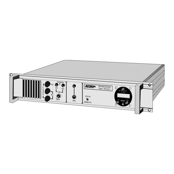
- Page 1 Technical Handbook and Maintenance Manual TR6101 VHF Ground to Air Radio Transceiver 3280 TJODALYNG, NORWAY...
- Page 2 JOTRON electronics a.s. December, 99 Page 2...
- Page 3 AMENDMENT RECORD AMDT INCORP. DATE PAGE(S) AMDT INCORP. DATE PAGE(S) 11.9.95 29,45,46,79,80 25.3.96 19.11.96 74 25.9.97 11 20.04.99 EM3215 JOTRON electronics a.s. December, 99 Page 3...
- Page 4 JOTRON electronics a.s. December, 99 Page 4...
- Page 5 On no account must these transistors be destroyed or discarded with industrial or domestic waste, but should be returned to the manufacturers for subsequent disposal. JOTRON electronics a.s reserves the right to make changes without further notice to any products or modules described herein to improve reliability, function or design.
- Page 6 JOTRON electronics a.s. December, 99 Page 6...
-
Page 7: Table Of Contents
ONNECTING ONE TRANSCEIVER TO A 6.3. C RC-3104...................36 ONNECTING TWO TRANSCEIVERS TO A 6.4. C RC-3401 .....................37 ONNECTING ONE TRANSCEIVER TO A 6.5. C RC-3401...................38 ONNECTING TWO TRANSCEIVERS TO A 7. PARTS LISTS ..............................39 8. DRAWINGS ..............................73 JOTRON electronics a.s. December, 99 Page 7... -
Page 9: Technical Data
Humidity: 90% at 40 C without moist. ª Shock: (Transport) IEC-721-3-2, Class 2M3 Vibration: (Transport) IEC-68-2-32, Class 2M3 IEC-68-2-6 Dimension: 19” standard rack. 405mm (W) * 250mm (D) * 88 mm (H) Weight: 6,5 kg JOTRON electronics a.s. December, 99 Page 9... -
Page 10: Receiver Data
Loudspeaker: Max. 1 W, 10 ohm, adjustable by volume controls. Line: Adjustable from -20 to + 10 dBm. Ri = 600 . Floating transformer with centre tap. Distortion: Less than 5% with 70% modulation, 100mV RF input signal. JOTRON electronics a.s. December, 99 Page 10... -
Page 11: Transmitter Data
Microphone input , 5mV sensitivity. Supply voltage: 24 V to 32 V. Permissible mismatch: VSWR 1 : 3. Harmonic distortion: Less or equal than 1*10-5 W Spurious output: Less or equal than 1*10-7 W JOTRON electronics a.s. December, 99 Page 11... - Page 12 JOTRON electronics a.s. December, 99 Page 12...
-
Page 13: External Connections
Indicates that there is a RF signal going out on the antenna connector. The intensity of the light varies slightly with the modulation level, that means the LED can be used as an indicator for the modulation level. JOTRON electronics a.s. December, 99 Page 13... - Page 14 7In remote, audio and key signals are taken from the 600 remote line input/output. The 600 remote line will also output the received audio in when the switch is in remote position. The built in loudspeaker will be connected in either position of the switch. JOTRON electronics a.s. December, 99 Page 14...
- Page 15 By turning the knob clockwise the volume of the internal loudspeaker is increased. The knob has no effect on the line output level. SQUELCH button. The SQUELCH button toggles the squelch on and off. Squelch level is preset by an internal pot. meter. JOTRON electronics a.s. December, 99 Page 15...
-
Page 16: Rear Panel Connections
The transceiver must be in REMOTE position to use the line. The transceiver can also be keyed with this line by using line loop keying (making a DC path between the two lines). JOTRON electronics a.s. December, 99 Page 16... - Page 17 IC3 on the remote control interface and the driver unit has been modified accordingly. With this option installed, it is possible to control 6 channels from a remote position with the remote control RC-3401. JOTRON electronics a.s. December, 99 Page 17...
- Page 18 The pin is the most significant bit of the remote channel selection. A TTL signal is used to set the channel, the signal is active low (0V) referred to GND (pin 14). The signal is pulled up internally. NO CONNECTION NO CONNECTION NO CONNECTION JOTRON electronics a.s. December, 99 Page 18...
- Page 19 AC is input between A and C, B is chassis ground. The voltage should be 230VAC ± 10% or optionally 115 ± 10%. To use 115VAC the transceiver must be rewired internally, see WIRING DIAGRAM for details. JOTRON electronics a.s. December, 99 Page 19...
- Page 20 JOTRON electronics a.s. December, 99 Page 20...
-
Page 21: Installation
The display only has 5 digits, that means some frequencies may be truncated. However, the frequency step is always 25 kHz. For example does 132.32 mean 132.325 MHz. JOTRON electronics a.s. December, 99 Page 21... -
Page 22: Changing The Operating Frequency
600Ω line input, by applying a DC voltage to rear connector pin 2 (REMOTE KEY DC INPUT), or by grounding rear connector pin 7 (REMOTE KEY GND INPUT). When the transceiver is keyed, the carrier indicator will light and the receiver will be muted. JOTRON electronics a.s. December, 99 Page 22... -
Page 23: Internal Adjustments
Then clockwise until no noise is heard, i.e. squelch is closed. • Replace the top cover of the transceiver. JOTRON electronics a.s. December, 99 Page 23... -
Page 24: Modulation And Power Adjustment
In the TR-6201, transmitter unit, there is an automatic detector that selects between an external feedback signal and the internal signal. This means that if the output of the driver unit is JOTRON electronics a.s. December, 99 Page 24... - Page 25 The modulation should be adjusted to app. 80-85% with this input signal. • Check that the distortion of the output signal is below 5%. • Alternatively, the modulation could be checked with an RF oscilloscope. • Replace the top-cover of the transceiver. JOTRON electronics a.s. December, 99 Page 25...
- Page 26 JOTRON electronics a.s. December, 99 Page 26...
Need help?
Do you have a question about the TR6101 and is the answer not in the manual?
Questions and answers