Table of Contents
Advertisement
Quick Links
Advertisement
Table of Contents

Summary of Contents for NDE Pool MASTER PLUS NDE-08-DCP
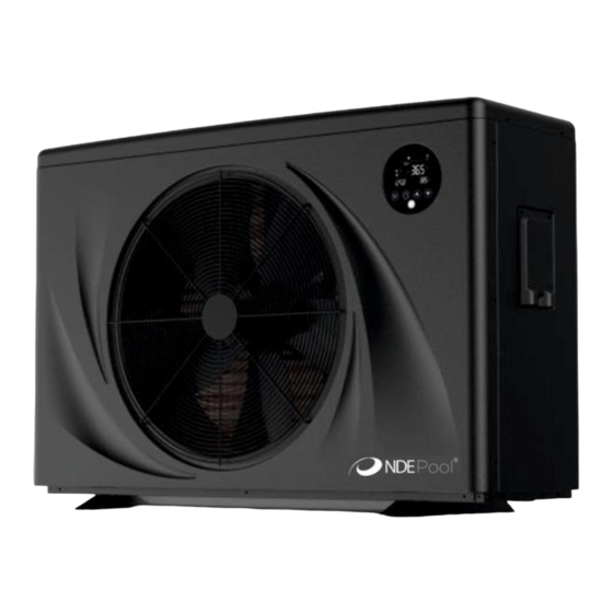
- Page 1 DC Inverter Swimming Pool Heat Pump User and Service manual MASTER PLUS - 1 -...
-
Page 2: Identification Data
INTRODUCTION: Thank you for purchasing the “NDE Master Plus” heat pump manufactured to the highest standards. This user and maintenance manual is a document issued by NDE GROUP in relation to the products to which it refers, it is to be considered an integral part of the product itself for its whole life, even in case of eventual sale to third parties, up to the demolition and disposal of the same. - Page 3 Pool Heat Pump User and Service manual INDEX 1. Specifications 2. Dimension 3. Installation and connections 4. Accessories 5. Electrical Wiring 6. Display Controller Operation 7. Running data setting 8. Troubleshooting 9. Maintenance 10. WIFI Controller Function Specification - 3 -...
- Page 4 Thank you for using swimming pool heat pump for your pool heating, it will heat your pool water and keep a constant temperature when the ambient air temperature is between -15 to 43ºC. ATTENTION:This manual includes all the necessary information about the use and the installation of your heat pump.
-
Page 5: Specifications
1. Specifications 1.1 Technical data NDE-08-DCP NDE-10-DCP NDE-11-DCP NDE-14-DCP Product model Advised pool volume (m3) (with cover) 15~30 20~40 25~50 30~60 -7 ~43 Operating ambient temperature range(℃) Heating capacity 7.50~1.92 9.50~2.10 11.00~2.50 14.00~3.15 (kW) 25500~6528 32300~7140 37400~8500 47600~10710 Heating capacity (BTU/h) heating* Input power (kW) 1.15~0.13... -
Page 6: Product Model
NDE-17-DCP NDE-20-DCP NDE-24-DCP Product model Advised pool volume(m3) (with cover) 40~75 55~100 60~110 Operating ambient temperature range(℃) -7 ~43 Heating capacity (kW) 17.00~3.75 20.00~4.00 24.00~4.80 Heating capacity (BTU/h) 57800~13090 68000~13600 81600~16320 heating* Input power (kW) 2.62~0.25 3.33~0.27 4.00~0.32 6.5~15.0 6.0~14.8 6.0~15.0 COP at 50% capacity 11.00... - Page 7 2. Dimensions 2.1 Unit mm NDE-08-DCP Model / NDE-10-DCP NDE-17-DCP Units NDE-24-DCP NDE-11-DCP NDE-20-DCP (mm) NDE-14-DCP 1106 - 7 -...
- Page 8 Exploded views NDE-08/10/11/14/17/20/24-DCP - 8 -...
-
Page 9: Installation And Connection
3. Installation and connection 3.1 Notes The factory only supplies the heat pump. All other components, including a bypass if necessary, must be provided by the user or the installer. Attention: Please observe the following rules when installing the heat pump: 1. - Page 10 3.3 Distance from your swimming pool The heat pump is normally installed within a perimeter area extending 7.5 m from the swimming pool. The greater the distance from the pool, the greater the heat loss in the pipes. As the pipes are mostly underground, the heat loss is low for distances up to 30 m (15 m from and to the pump;...
- Page 11 3.6 Adjusting the bypass Use the following procedure to adjust the bypass: • fully open all three valves • slowly close valve 1 until the water pressure is increased by To pool From pool approximately 100 to 200 g • Close valve 3 approximately half- way to adjust the gas pressure in the cooling system...
- Page 12 Note: In the case of three-phase models, swapping two phases may cause the electric motors to run in the reverse direction, which can lead to damage. For this reason, the unit has a built- in protective device that breaks the circuit if the connection is not correct. If the red LED above this safety device lights up, you must swap the connections of two of the phase wires.
- Page 13 restart automatically (as long as the filter pump is running) whenever the swimming pool water temperature drops 2 degrees below the set temperature. Depending on the initial temperature of the water in the swimming pool and the air temperature, it may take several days to heat the water to the desired temperature. A good swimming pool cover can dramatically reduce the required length of time.
- Page 14 Water Inlet & outlet junction 1. Use the pipe tape to connect the water Inlet & outlet junction onto the heat pump 2. Install the two joints like the picture shows 3. Screw them onto the water Inlet & outlet junction Cable wiring 1.
- Page 15 5. Electrical Wiring 5.1 DC INVERTER SWIMMING POOL HEAT PUMP WIRING DIAGRAM - 15 -...
-
Page 16: Display Controller Operation
NOTE: (1)The above electrical wiring diagrams are only for your reference, please subject the heat pump to the posted wiring diagram. (2)The swimming pool heat pump must be earthed well, although the unit heat exchanger is electrically isolated from the rest of the unit .Earthing the unit is still required to protect you against short circuits inside the unit .Bonding is also required. - Page 17 6.3 Remote Controller(LCD Wire controller(with WIFI)) ◎ Basic Icons Heating mode, display symbol “ ” Cooling mode, display symbol “ ” When water pump is running,display symbol “ ” “Powerful” operation mode,display symbol “POWERFUL” “Silent” operation mode,display symbol “SILENT” “Smart” operation mode,display symbol “SMART” When compressor is running,display symbol “...
- Page 18 6.4 Key Operating Instruction 6.41 “ ”: ON /OFF button. Short press “ ” to exit and return to the main interface. In the main interface, long press and hold the “ ” key for 3 seconds to turn on / off. 6.42 “...
- Page 19 6.47 Clock setting: Press the “ ” button to enter the clock setting state. First, the hour bit flashes, indicating that the hour value of the current time can be adjusted through the “ ”, “ ” buttons. Every time you press the “ ”...
-
Page 20: System Parameter
6.52 Operation mode switching: Long press “ ” and “ ”on the main interface for 3 seconds to switch operation mode: Powerful, Smart and Silent mode. 6.53 Celsius / Fahrenheit switch: In the off state, press “ ” and “ ”... - Page 21 Working Cycle Overheat Degree in Smart/ -5℃~10℃(-9~20℉) Depends on Powerful Mode Actual Model Exhaust Gas Temp. of 70℃~125℃(158~257℉) 95℃(203℉) Electronic Expansion Valve Electronic Expansion Valve's Depends on Steps during Defrosting 2~45 Actual Model (Set Value*10=Actual Steps) Electronic Expansion Valve's 5~15 Min.
-
Page 22: Troubleshooting
8. Troubleshooting 8.1 system protection/ error indication error code error description Solutions Er 03 water flux failure Check water flow /switch Water pump will run automatically for first grade Er 04 winter anti-freezing antifreeze 1. Discharge redundant refrigerant from heat pump Er 05 high pressure failure gas system... - Page 23 Keep the ambient temperature within the normal Outdoor coil too high temperature Er 33 operating ambient temperature range of the protection machine 1. Check if the incoming voltage supply is too low, if so, repair. Er 35 Compressor current protection 2.
- Page 24 Input three phase imbalance AC Input over- Inspection input three (three phase module is current phase phase voltage effective) AC Input low Input low voltage Inspect input voltage voltage Compressor High Compressor high pressure pressure failure failure (reserved) IPM too high Main unit fan motor failure, air Inspect fan motor and temperature...
-
Page 25: Maintenance
1. Check the cable connections between the motor and fan, if necessary, LED displays 1. Fan NOT running they should be replaced actual water Short 2. Not enough air 2. Check the location of the temperature, no running ventilation heat pump, and eliminate all error code 3.Not enough refrigerant obstacles to assure a good... - Page 26 WIFI Controller Function Specification Step 1. Download APP Search and download “Smart Life” In major Application markets or Scan the QR Code below to download the App Sept 2. Registration /Login/password retrieval Registration If you do not have app account, you may choose to register or log in by authorization code.
- Page 27 5.2 Login If you already have an app account, please click "Log in" to enter the login page. Enter your registered mobile phone number or email, enter the password in to log in Sept 3. Add device You have two Wi-Fi connection options. Default mode and compatibility mode. Default mode operation 3.1 Default mode operation - 27 -...
- Page 28 ” at the same time for 3 seconds to enter the "default ”“ press and hold the“ ”icon will flashing fast mode" to connect the Wi-Fi, the“ Open “Smart life” App,Click“ ”in the Upper right corner or “Add device” on the interface, Select“Water heater(WI-FI)”...
- Page 29 Input Wi-Fi Password (must be consistent with the Wi-Fi connected to the mobile phone), Click “next” enter the device connection status directly; When the connection is successful, and the system prompts "added successfully ", then click “Done” to directly enter the device operation main interface. If Default mode connection not successful, Try Compatibility mode.
-
Page 30: Compatibility Mode
3.2 Compatibility mode press and hold the “ ”“ ”at the same time for 3 seconds, the “ ”icon will be flashing slowly. Open “Smart life” App, Click “ ”in the Upper right corner or “Add device” on the interface, Select “Water heater(WI-FI)” in ”Large appliance” to enter the Wi-Fi Connection interface Input Wi-Fi Password (must be consistent with the Wi-Fi connected to the mobile phone), Click “next”... - Page 31 Click “EZ Mode” to switch to “AP mode”, Click “Confirm indicator slowly blink”, Click “Next” And it pops up ”Connect your mobile phone to the device’s hotspot”, Click “go to connect. Enter the Wi-Fi Connection interface, find and connected The desired Wi-Fi Hotspot, For examples, as pic 1 ”Smartlife_3C4A,”, Click for Connection, APP will automatically enter the device connection state;...
- Page 32 Step 4. App operation introduction After the device is successfully bound to enter operation page 4.1 Start / Stop the heat pump press button to the heat pump on or off. - 32 -...
- Page 33 4.2Set target water temperature Set the target temperature by sliding the dot 4.3 Mode setting In the main interface, click ” ” The mode selection interface will pop up as shown below, just click the mode you want to select - 33 -...
- Page 34 4.4 Timer setting In the main interface, click” to enter timer setting, click to add timing - 34 -...