
Related Manuals for Seada TapPlay TP-U400

Summary of Contents for Seada TapPlay TP-U400
- Page 1 TapPlay™ User Manual TP-U400 Receiver: TP-U400 Transmitter: TP-DGH (HDMI dongle), TP-DGC (Type C dongle) Document No. SD-MA-044 Document Version: 02...
-
Page 2: Table Of Contents
Contents Overview ................................1 Specification ..............................4 Panel Layout ..............................5 Hardware Interface ........................... 5 3.1.1 TP-U400 Front Panel .......................... 5 3.1.2 TP-U400 back Panel ........................... 7 3.1.3 Factory Reset ............................. 8 3.1.4 Dongle Front Panel ..........................9 Software Interface ........................... 11 3.2.1 Home Screen ........................... - Page 3 Whiteboard & Annotation ....................... 22 5.5.1 Whiteboard ............................. 22 5.5.2 Annotation ............................25 Start video conferencing via USB-over-Wi-Fi technology ................27 Start with application/dongles ......................27 WEBUI ................................28 Network settings ..........................29 7.1.1 Wireless network ..........................29 7.1.2 Ethernet ............................32 7.1.3 Auto change password ........................
- Page 4 Firmware upgrade ........................... 50 7.6.1 Firmware Update ..........................50 7.6.2 Automatic Upgrading ........................50 Other settings ..........................51 7.7.1 Auto create launcher ........................51 7.7.2 Clear history after meeting......................52 7.7.3 Developer tools ..........................52 UCC-Device manager ........................53 About device ............................ 54 Troubleshooting .............................
-
Page 5: Overview
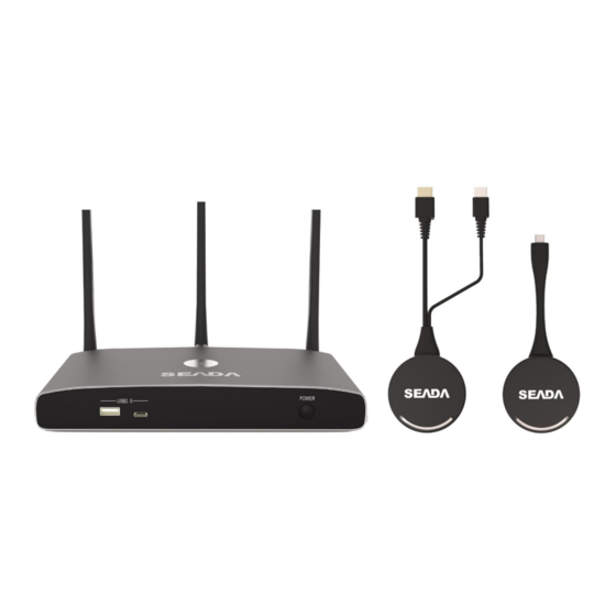
Overview TP-U400 is a BYOM wireless presentation switcher designed for ease of use in conference room or classroom applications with less cabling and cost. This product is compatible with most USB cameras and conferencing audio solutions, such as speakerphones, AEC processors, video soundbars with audio integration, etc. - Page 6 TP-DGC/TP-DGH: • Support wireless transmission from PC/Mac to base unit • Support quick switch of the PC signal for less than 1s by tapping • Dual color LED, indicating active source signal and power/link • Support USB peripherals such as camera, mic, and speaker over Wi-Fi sharing TP-U400 related devices and applications A typical TP-U400 can work with two different types of dongles, ‘TapPlay’...
- Page 7 Name Description Base Unit Base unit TP-U400 For PC/Mac to share the desktop/extended Dongles/Transmitters desktop. For Android/Windows/Mac devices to share ‘TapPlay’ app the screen. Airplay for IOS For IOS devices to share the screen. Accessories List Name Description 3 pcs of antenna are included in the box. To avoid damage, they are not pre-mounted.
-
Page 8: Specification
Specification TP-U400 Specification HDMI output 1x HDMI 19-pin female connector Video Output Resolution 3840x2160@60Hz/30Hz, 1920x1080@60Hz, 1280x720@60Hz Format Compliance HDMI1.4/HDMI2.0 HDMI input / max. resolution Maximum 1080P@60Hz via TP-DGH/DGC, app, and Airplay HDCP HDCP1.4/HDCP2.2 Compatible dongles TP-DGH, TP-DGC LAN port 2x RJ45: 1x 1000Mbps with POE, 1x 100Mbps USB interface 3x USB3.0, 1x USB 2.0, 2x Type-C Control... -
Page 9: Panel Layout
3. Panel Layout About this chapter The installation chapter gives an overview of the interface of TP-U400 Overview ⚫ Hardware Interface ◼ TP-U400 Front Panel ◼ TP-U400 Back Panel ◼ TP-DGH/TP-DGC Front panel ⚫ Software Interface ◼ Home Screen Hardware Interface 3.1.1 TP-U400 Front Panel Note: Front USB port and type C port cannot be used at the same time, type C port is prior to USB... - Page 10 Name Description USB port, for dongle pairing, mouse control, Front USB connector USB touch screen etc. Front Type-C connector Type-C port, for dongle pairing. Power Button Turn on or off the device. RED: Initialisation Flashing GREEN: Power on Back-lit LED indicator Static GREEN: Ready to share Static Cyan, Sharing USB port...
-
Page 11: Tp-U400 Back Panel
3.1.2 TP-U400 back Panel Name Description Line audio 2 channel analog audio output output RS-232 RS-232 port Kensington Standard Kensington Lock to security the unit Lock Rear Type-C Type C port for TP-DGC pairing connector USB port for TP-DGH pairing, mouse control, USB touch Rear USB3.0 screen and USB device such as USB camera and speaker connector... -
Page 12: Factory Reset
LAN Ethernet 100Mbps Ethernet port port 1 LAN Ethernet 1000Mbps Ethernet port and support POE port 2 DC Power Power socket to boot up the unit socket Antenna Screw up the included three antennas to these three fixture points ports. USB port ⚫... -
Page 13: Dongle Front Panel
3.1.4 Dongle Front Panel TP-DGH (left) and TP-DGC (right) are dongles, used for toggling the mirroring from personal PC or Mac onto the main screen. ⚫ When LED indicator is static green, it’s ready to mirror desktop onto the main screen. ⚫... - Page 14 Type C (DP) Type C (DP) connector of the dongle can be plugged connector into a PC/Mac for sharing screen. Touch the sensor button to start mirroring desktop Touching onto the main screen. Touch again the sensor button to button terminate the sharing.
-
Page 15: Software Interface
Software Interface 3.2.1 Home Screen Name Description Wi-Fi Direct mode: Access point is enabled: Wi-Fi Infrastructure mode: Wi-Fi connection to router is established and the icon displays the current signal strength: · Wi-Fi Indicator A secure Wi-Fi connection is established, or connection to a router failed: Wi-Fi is not available: LAN Infrastructure mode: Access point is disabled... - Page 16 Display time until the password changes Password-timer automatically. This timer is only available when ‘auto change password’ is activated. Refresh Wi-Fi- Generate a new password manually to secure the password Wi-Fi network. Show time if LAN/Wi-Fi has access to a time server. The time is displayed until the device power is cut TIME after...
-
Page 17: Installation
4. Installation This section gives an overview of the ways to install and connect the base unit. Installation methods for the base unit Introduction to the installation methods: The base unit can be installed either by table mounting or wall mounting in a meeting room. The articulated antennas are removable and rotatable for easier connection and better signal. -
Page 18: Wiring Diagram
Wiring Diagram Power Connection The base unit can be powered by external power adapters. How to connect the external power adapter 1. Connect the power adapter with the power lead and plug it into the power input of the base unit. 2. -
Page 19: Video Connection
Video Connection 1. Connect the HDMI Output of the base unit to a 4K or Full-HD display by a HDMI cable. 2. Connect the power adapter to the base unit DC power socket, connect the power plug to an outlet and switch the base unit on. 3. -
Page 20: Use Of Usb Devices
Use of USB devices USB control: A USB mouse or touch screen can be connected to the base unit. USB mouse ⚫ For configuration of the home screen. ⚫ Single click to select. ⚫ Right-click to back to the Home Page. ⚫... -
Page 21: Quick Start
5. Quick Start Mobile device: Wireless Connection 1. Connect the mobile device to the base unit via WiFi and type in the WiFi IP of the base unit in any browser. Then download the application named ‘TapPlay-Android.apk’. 2. For IOS devices, use Airplay to mirror the desktop. Pairing dongles with base unit 1. - Page 22 5. User can right-click the status icon in Windows taskbar to open up the menu. • ‘About’: User can check the version of the base unit, the dongle, and the application. • ‘Exit’: Exit the application. For the first time user, when the application detects TP-U400 is connected with a camera/microphone/speaker, a message box will pop up indicating that a virtual drive needs to be installed.
-
Page 23: Options For Windows Pc/Mac
5.3.1.1 Options for Windows PC/Mac Click the icon in the window to open/close ‘Options’. ⚫ Extended Screen: Transfer extended desktop of the active source. (Depending on the operating system, it may require the installation of a virtual driver called ‘Extended Display’). The primary screen is displayed on the laptop and the extended screen is displayed on the main screen. -
Page 24: Mobiles Devices
5.3.2 Mobiles Devices Sharing on Android devices 1. Download the ‘TapPlay-Android.apk’ application. 2. Connect mobile device to the same network as the base unit. 3. Open the application in the mobile device, and the homepage will pop up. Click the device list refresh button to get the list of devices. -
Page 25: Miracast On Android Devices And Win10 Pc
5.3.3 Miracast on Android Devices and WIN10 PC Android Devices 1. Make sure WiFi or WLAN is enabled. 2. Swipe down the top of phone’s screen and click the wireless projection icon in the popup page. 3. The wireless projection window will pop up and find the base unit in the available list to connect. 4. -
Page 26: Preview Window
Preview Window On touchscreen or with mouse connected to the base unit, the ‘Left’ and ‘Right’ arrow on the right of home screen can be used to display or hide the preview. By default, the preview window will be hided and when a USB device is connected, it will pop out for 20 seconds until it is hidden again. - Page 27 Use the toolbar to select one of the following functions. Icons Function Tool bar 1 Add an empty page Delete the current page Display previous or next page Tool bar 2 Undo: one step backward in changes Redo: one step forward in changes Erase part of writing/drawing Clear the entire writing/drawing on the screen Pen for writing/drawing in different colors...
- Page 28 This window will pop up, when ‘Pen’. ‘Draw shape’ or Tool bar 3 ‘Select color of board’ is selected, for change of the size and color. Tool bar 4 Save the current screenshot on local storage. Close the whiteboard to go back to the home screen. The current project can be saved on local storage.
-
Page 29: Annotation
5.5.2 Annotation Use the toolbar to select one of the following functions. Icons Function Tool bar 2 Undo: one step backward in changes Redo: one step forward in changes Erase part of writing/drawing Clear the entire writing/drawing on the screen Pen for writing/drawing in different colors Select color of the board Tool bar 4... - Page 30 Close the whiteboard to go back to the home screen. The current project can be saved on local storage. Download drawings to connected users Scan the QR-code with the camera of the mobile or enter the given IP-address in a browser. If the network connection is set properly, the saved files on the base unit can be accessed, which can be downloaded as PNG files.
-
Page 31: Start Video Conferencing Via Usb-Over-Wi-Fi Technology
6. Start video conferencing via USB-over-Wi-Fi technology This function allows starting video conferences easily with PC, and at the same time utilise the room USB peripherals like camera, microphone, and speaker to have a better AV experience. Start with application/dongles 1. -
Page 32: Webui
7. WEBUI Connect the base unit to the PC/Mac and enter the IP address of the base unit in any browser to access the WebUI. All the applications for TapPlay can be downloaded here. Note: It is recommended to restart base unit at least 1 min after any modification on the setting. Click Setting button on the top right corner to enter the WebUI. -
Page 33: Network Settings
Network settings 7.1.1 Wireless network This wizard allows the user to create a customised configuration for integration of the base unit into existing wireless infrastructures. Wireless network configuration wizard Enter a device name for the base unit. The default name is ‘TapPlay-XXXX’. Click ‘Next step’. - Page 34 Click ‘Next step’ to edit the GUEST network SSID for direct connection and STAFF network SSID for LAN connection. This information will be shown on the home screen. Click ‘Submit settings’ to finish configuration and re-pair the dongles with the base unit. Wireless Infrastructure mode The base unit can be connected to a wireless network.
- Page 35 Click ‘Next step’ to edit or change Guest network SSID and Staff network SSID. Wi-Fi name of guest and staff will be shown on the home screen after clicking ‘Submit settings’ and re-pair the dongles with the base unit. LAN Infrastructure Mode In this mode, the built-in Wi-Fi access point of the base unit is disabled User can connect to the secured wireless access point of the company network.
-
Page 36: Ethernet
7.1.2 Ethernet Configure the Ethernet settings. By default, Ethernet setting of the base unit will be on DHCP. SD-MA-044 V2.0... -
Page 37: Auto Change Password
7.1.3 Auto change password The password will keep unchanged while at least one dongle or a PC/Mac/mobile device is connected to the base unit. After it is disconnected, the password will change in a given period. Click to change the given time when the WiFi password will be changed automatically, including ⚫... -
Page 38: Display & Audio
Display & Audio 7.2.1 HDMI HDMI Resolution Select the resolution for the HDMI output of the base unit. Note that the resolution that is not supported by the display will not be shown in the list. ⚫ Auto ⚫ 3840x2160 @30Hz ⚫... - Page 39 HDMI CEC The base unit supports CEC if the connected display supports CEC. ⚫ Device auto power off: ◼ ON (Default): When the base unit goes into standby mode, it will send commands via the HDMI cable to turn off the display as well. ◼...
-
Page 40: Audio
7.2.2 Audio Audio: Choose audio output: Jack: Output only 3.5mm mini-jack audio. HDMI: Output only HDMI audio. Jack & HDMI (Default): Output Jack & HDMI audio Audio Volume: User can select volume from 0 to 100. SD-MA-044 V2.0... -
Page 41: Airplay Screen Quality
7.2.3 Airplay screen quality Select the image quality when the screen of Apple device is mirrored by ‘Airplay’. SD-MA-044 V2.0... -
Page 42: Show The Base Device Name And Password When Mirroring
7.2.4 Show the base device name and password when mirroring: Name (ID) and Wi-Fi-password will be shown or hided at the top of the home screen when mirroring. Show PC’s username when mirroring: Show username of the device that are being mirrored. Hide SSID/Code when using an individual background image: Hide the SSID information when user has changed the background image from the default one. -
Page 43: Home Screen Background Image
7.2.5 Home Screen background image When powering up the base unit, the home screen will be displayed. User can change the background picture in this option. The format can be jpg, bmp, png or gif with resolution 1920x1080P) SD-MA-044 V2.0... -
Page 44: Moderator Control
Moderator control Moderator sidebar: Hide side bar completely (including arrow) – Hide the preview side bar completely. Small menu (no preview windows) – Show the preview side bar without preview windows. Large menu (show preview windows) – Show the preview side bar. Real time preview: By ticking the option, the preview window will show real time preview. - Page 45 Multiview Layout: Choose from preset layouts for displaying the shared windows on screen. SD-MA-044 V2.0...
-
Page 46: System Settings
System settings 7.4.1 Buttons: Show Device name, MAC Address, Serial Number, Device Version, Device Status, Last Action and Item Operate of the connected devices. Paired: Show properties of the connected dongles. SD-MA-044 V2.0... -
Page 47: Date & Time
7.4.2 Date & Time ⚫ Automatic date & time: Use an NTP time server to provide time as system time. ⚫ Set date: Manually enter the date. ⚫ Set time: Manually enter the time. The setting will not be saved after the power is off. ⚫... -
Page 48: Auto Standby
7.4.3 Auto standby If the auto standby mode is activated, the base unit will automatically switch to power saving mode after a given time. The time is selectable from Never to 30 minutes. In standby mode, the green LED on the top of the base unit will flash and the HDMI output will be switched off. -
Page 49: Reset
7.4.5 Reset Reset the base unit. 7.4.6 Configuration File Configuration file is a packaged file which contains all the configuration for the base unit, which can be downloaded and uploaded to another device which needs to have the same configuration. SD-MA-044 V2.0... -
Page 50: Series Port Setting
7.4.7 Series Port Setting Configure telnet command and RS-232 command. 7.4.8 Telnet switch Switch the telnet function ON or OFF. SD-MA-044 V2.0... -
Page 51: Reboot
7.4.9 Reboot User can set up timing reboot for the base unit. SD-MA-044 V2.0... -
Page 52: Security Settings
Security Settings 7.5.1 Security level Based on user requirements, three different security levels can be set to satisfy different requirements according to different security environments or security policies. There is also a customised security level for the users to set their own. The default setting is level 1. -
Page 53: Login Password
7.5.2 Login Password Change admin password for WebUI. The default password after reset is ‘admin’. 7.5.3 Connection password Two type of password format can be chosen to show on the home screen. 4-digits password: beginning with 0000 8-digits password SD-MA-044 V2.0... -
Page 54: Firmware Upgrade
Firmware upgrade 7.6.1 Firmware Update To upgrade the firmware of the base unit. 7.6.2 Automatic Upgrading Tick to choose upgrading from OTA via Internet or from local files. SD-MA-044 V2.0... -
Page 55: Other Settings
Other settings 7.7.1 Auto create launcher When this function is enabled, if a USB stick is plugged into one of the USB ports of the base unit, all the application will be automatically copied into the USB stick. SD-MA-044 V2.0... -
Page 56: Clear History After Meeting
7.7.2 Clear history after meeting Pictures, videos, and music of the connected devices will be stored in the storage of the base unit. This storage can optionally be erased when the device is disconnected. Decide by User: When all devices and dongle are disconnected from the base unit, a window will pop up on the display to ask whether to clear the meeting history. -
Page 57: Ucc-Device Manager
UCC-Device manager USB-Camera: When there are multiple USB cameras connected to the base unit for virtual meeting purpose, user can choose from the list which camera is activated. USB-Audio: When there are multiple speakers/microphones connected to the base unit for virtual meeting purpose, user can choose from the list which speaker/microphone is activated. -
Page 58: About Device
About device Check the firmware version of the base unit and WEBUI. SD-MA-044 V2.0... -
Page 59: Troubleshooting
8. Troubleshooting Below are some fundamental issues that might happen and possible causes and solutions. Problem Cause Solution Use “TapPlay-Android” application in Wi-Fi password of base unit changed Reconnect the mobile device by Android device or Airplay on IOS when android or IOS device is entering password showed on home device, and it can’t find base unit connected to the Wi-Fi of base unit. - Page 60 ⚫ ⚫ Bad connection at USB port on Reconnect to the USB port the PC/Mac ⚫ Try another USB port ⚫ Reboot the PC/Mac ⚫ The software might be blocked If possible, add the software to the by the anti-virus software on the trust list of the anti-virus software or PC/Mac close the anti-virus software.
- Page 61 No Wi-Fi connection between mobile Wrong Wi-Fi frequency Check mobile device to select the device with the base unit correct 2.4GHz or 5GHz Wrong SSID and password Enter the correct SSID There is no sound on the main screen No connected audio device. Make sure, the audio is turned on.
Need help?
Do you have a question about the TapPlay TP-U400 and is the answer not in the manual?
Questions and answers