Table of Contents
Advertisement
Quick Links
Advertisement
Table of Contents

Related Manuals for emmeti FEBOS - CRONO IMX Basic / WiFi

Summary of Contents for emmeti FEBOS - CRONO IMX Basic / WiFi
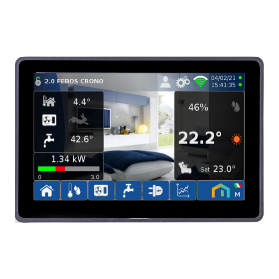
- Page 1 FEBOS - CRONO IMX Basic / WiFi (Software V. 3.0.1) INSTALLATION AND USE MANUAL...
-
Page 2: Table Of Contents
® All rights reserved. No part of this pubblication may be reproduced or distributed without written permission from Emmeti. Warning! Keep these manuals in a dry place avoiding in this way to spoil them. -
Page 3: Presentation
1. PRESENTATION Scheme of the Integrated Management System the plant management algorithms can be set. The integrated management of the thermal system and heat pump To complete the functions present in the SMART-MT it is possible to (HP) is carried out through an innovative SMART-MT regulator sup- connect, to the PCB-Terminal Block, a normal room thermostat for plied with it. - Page 4 1. PRESENTATION FEBOS 4.0 Is a new modular Hardware / Software platform developed for the management of the MIRAI SMI heat pump and the control of room comfort and the related flows and energy costs of the residence. This platform consists of the following field devices: Febos-Crono (BASIC/WiFi), Febos-Energy, Febos-Power and Febos-Relay and a Cloud dedicated to their management.
- Page 5 1. PRESENTATION FEBOS-CRONO basic User terminal for controlling room temperature and humidity and displaying and/or setting the MIRAI SMI 4.0 heat pump operating parameters. MIRAI SMI 4.0 Web App FEBOS-CRONO WiFi / FEBOS-CRONO 360° connectivity. Tablet or PC This is what makes the Febos-Crono world truly complete, the plug in WiFi.
-
Page 6: Warnings And Technical Data
2. WARNINGS AND TECHNICAL DATA SAFETY WARNINGS Read this manual carefully before use and keep it for future reference. Carefully read the manual supplied with the MIRAI SMI 4.0 heat pump • Installation must be carried out by a qualified •... - Page 7 3. INSTALLATION...
- Page 8 3. INSTALLATION TABLE OF CONTENTS...
-
Page 9: Installation
3. INSTALLATION 3.3 Wall mounting Installazione a parete The FEBOS-CRONO can be fixed to the wall in two ways: flush with the wall or on a recessed box. Il FEBOS-CRONO dev’essere installato ad una altezza di 1.5m dal pavimento in un luogo asciutto esente da correnti The FEBOS-CRONO must be installed at a height of 1.5m from the floor in a dry place free of air currents, away from heat sources ( d’aria, lontano da fonti di calore ( termosifoni , climatizzatori, finestre) in una posizione significativa per il controllo radiators , air conditioners, windows) in a position significant for the control of the room comfort as follows. -
Page 10: First Start-Up
4. FIRST START-UP SERVICE ATTENTION At the first power supply of the Febos-Crono you need to wait For the following procedures, log on as Service a few minutes before turning on the display. Also you need to perform in sequence the following steps: The factory configuration includes the MIRAI-SMI 4.0 HP and the 4.1 WiFi connection Febos-Energy, while no Febos-Crono Slave is available. - Page 11 4. FIRST START-UP SERVICE 4.2.1 System without HP The Modbus address must be configured on each Febos Crono- Slave. By deselecting the MIRAI-SMI 4.0 HP, the screens related to the Heat Pump and the Sanitary Hot Water are no longer accessible, and the relative values are no longer displayed on the Home page.
- Page 12 4. FIRST START-UP SERVICE 4.2.3 Centralized Slave 4.2.4 Independent Slave If Centralized Slave is selected, the consents from Thermostat and If Independent Slave is selected, the consents from Thermostat Humidistat, in addition to supplying power to the relay outputs and Humidistat supply power only to the outputs (24Vdc max 20mA), are sent to the Heat Pump, which then comes relay (24Vdc max 20mA).
-
Page 13: Setting Inputs Of The Electrical Powers
4. FIRST START-UP SERVICE c. Select the input used for each electrical 4.3 Setting inputs of the electrical powers power. For the correct measurement of electrical powers it is essential to associate to each power, the relative input. a. Press the icon then NOTE: If an electrical power is not managed (e.g. -
Page 14: Setting The Hp Model And The System Recipe
4. FIRST START-UP TABLE OF CONTENTS SERVICE 4.4 Setting the HP model and the System Recipe NOTE If changes are made in the 1.5 SET POWER screen, a restart of the FEBOS-CRONO is required. The restart occurs automatically For the correct operation of the Heat Pump and management of after 10 min, or immediate restart is possible by pressing the cor- the system it is essential to set the size of the installed HP and the responding icon on the HOME screen. - Page 15 4. FIRST START-UP SERVICE Enter the value corresponding to the Heat Pump model Enter the number of the Recipe you want to load. installed: Then press OK 0 = EH0618DC 1 = EH1018DC 3 = EH1618DC 2 = EH1218DC 4 = EH1718D3 Then press Ok NOTE: Pressing...
- Page 16 4. FIRST START-UP SERVICE Confirm with Ok And wait for the procedure to complete Upon completion of the procedure, the Recipe on the SMART-MT will correspond to the Recipe loaded from the database. f. Pressing on a parameter it is possible to manually modify the value...
- Page 17 4. FIRST START-UP SERVICE 4.5 Temperature sensor CALIBRATION procedure and ambient humidity Note: the following procedure can only be performed by a qualified Technical Assistance Center (TAC) when starting up the system for the first time. the screens will be in English if the display is cast in the language. Enter password: #### (service) Enter the offset value -12 End of calibration...
-
Page 18: Setup
5. SETUP SERVICE 5.1 Checking the HP inputs and outputs b. Press the icon to access screen 4.2 a.Press the icon to access the Heat Pump Set screen. of the I/O Status. c. Verification of the PCB TERMINAL BLOCK inputs. R1 out Check if the values displayed on the screen correspond to the physical status of the inputs in the HP. - Page 19 5. SETUP TABLE OF CONTENTS SERVICE d. Check the outputs of the PCB TERMINAL BLOCK. Press and for 5 min it will be possible to manually change the status of the outputs and check their physical status on the HP. R1 out T1 out T2 out...
-
Page 20: Screen - 1.12 Debug
5. SETUP SERVICE 5.3 Screen 2.3 ROOM SET - SERVICE 5.2 Screen - 1.12 DEBUG Press the icon then the icon Press the icon and scroll through the screens until 2.3. Press to reset the Factory configuration (the graphs are also reset) Presence contact configured: Normally open. - Page 21 5. SETUP SERVICE 5.3.1 - Room temp. differential 5.3.2 Booster Differential The Room temp differential applies to the Room Temperature The Booster Differential applies to the Room Temperature Set Set for the Thermostat call ( for calling the automatic Boost ( The consent shall be activated when: The logic of activating/deactivating the automatic Boost is com- •...
- Page 22 5. SETUP TABLE OF CONTENTS SERVICE 5.3.4 Room temp. probe Offset and room humidity probe Offset If a deviation is found between the room temperature and/or room humidity values measured by the device, and the actual values detected by a calibrated measuring instrument, an offset can be applied.
-
Page 23: Heat Pump Screens - Service
5. SETUP TABLE OF CONTENTS SERVICE 5.4 HEAT PUMP screens - SERVICE Screen 4.6 defines the Climate curve in heating. In addition, the maximum temperature of the hot water at the radi- ant system is set (Par. C541) Carefully read the manual that accompanies the Heat Pump before changing the values of the Previous screen following screens. - Page 24 5. SETUP TABLE OF CONTENTS SERVICE Screen 4.7 defines the climate curve in cooling. Cooling adjustment logic In addition, the minimum temperature of the cold water is set in the CASE 1 - Set 1 in normal operation. radiant system (Par. C542), to which is added the limitation on the = daily screed programming + Climate curve.
-
Page 25: Sanitary Hot Water Screens - Service
5. SETUP TABLE OF CONTENTS SERVICE 5.5 SANITARY HOT WATER screens 5.4.4 OFFSET – SERVICE For a correct calculation of the power output it is important that the water temperature probes of the HP are aligned with each Carefully read the manual that accompanies the Heat other. - Page 26 6. GENERAL USER SETTINGS TABLE OF CONTENTS USER Below are the additional screens/information that are available by accessing as User . After 2 minutes of inactivity of the touchscreen the “standby screen” is activated, which displays the room temperature and any state of alarm. The following icon is used to indicate where the screen must be touched to execute the instruction (It will not appear on the Febos-Crono display).
-
Page 27: General User Settings
Press the icon to access the settings. Guest access level , default without password. · , with password 2022 User access level Service access level , with the password supplied during the Emmeti course. To change the access level press the icon... - Page 28 6. GENERAL USER SETTINGS USER 6.3.1 Change of theme as desired 6.3.3 Language change To change the background colors press the icon To change the language press the icon Below are some examples of Blue, Green, Grey and Red: Colors available Then choose the language you want.
- Page 29 6. GENERAL USER SETTINGS USER 6.3.4 Name change 6.3.5 Date/Time Change To change the name associated with Febos-Crono press To change the date and time of the Febos-Crono press Then choose from the available names. Change the date and time of the Febos-Crono by pressing the arrows then press Ok.
-
Page 30: Wifi Connection (Febos-Crono Wifi Model)
6. GENERAL INFORMATION USER 6.3.6 Info In the Info screen it is also possible to set the brightness of the Press the icon to access the Info screen. . screensaver (which is activated after 2 minutes of inactivity of the touchscreen): - Max →... - Page 31 6. GENERAL INFORMATION USER NOTE: If the Febos-Crono is not connected, select the WiFi net- work from those available. Router address Then enter the password and press OK. VPN server address WiFi Mac Address Device number WiFi network name If the password has been entered correctly, the WiFi icon will turn Signal between Febos-Crono and router green and indicate the signal strength.
-
Page 32: User Visualization And Set-Up
Frame with the smartphone via a QR code reading App the following code: At the address https://emmeti.aq-iot.net (link to the QR CODE) you can access the Emmeti portal from which you can monitor a Febos-Crono WiFi, if correctly connected to the network. - Page 33 7. USER VISUALIZATION AND SET-UP USER To find the serial number and the Tun0 you can follow the procedure below: ATTENTION!!! The following operations must be performed only and exclusively on the FEBOSCRONO Master panel of a system (the screenshots should not be acquired and sent of any Slave terminals installed).
- Page 34 7. USER VISUALIZATION AND SET-UP USER 5. Once the search is complete, click on the "Info" button: 6. Read ID (serial number) and Tun0 and enter numbers as shown in the example.
-
Page 35: Heat Pump User Screens
7. USER VISUALIZATION AND SET-UP USER 7.2 Heat Pump User Screens 7.2.2 Screen 4.3 - Compressor limitations On screen 4.3 you can set compressor limitations to: On screen 4.1 HEAT PUMP the icon is now visible, • Limit the noise of the HP at certain times, for example at night as additional screens are available. -
Page 36: Electrical Power User Screen
7. USER VISUALIZATION AND SET-UP USER 7.3 Electrical Power User Screen 7.2.4 Screen 4.5 – Cooling water temperature On screen 4.5 it is possible to set the Target temperature of the On screen 6.1 ELECTRICAL POWERS the icon is now cooling water: visible, as an additional screen is available. -
Page 37: Screen 3.2 Alarm History
7. USER VISUALIZATION AND SET-UP USER 7.4 Screen 3.2 ALARM HISTORY 7.4.2 Heat Pump alarm history On screen 4.1 HEAT PUMP press the icon On the 2.1 ROOM SET and 4.1 HEAT PUMP screens the icon to access the alarm history is now visible 7.4.1 History of Febos-Crono alarms On the screen 2.1 ROOM SET, press the icon The following information is available on this screen:... -
Page 38: Guest Screens
8. GUEST SCREENS GUEST By default the access level is as Guest (guest), indicated by the icon The screens displayed and settings are limited, but still sufficient to manage the comfort environment. 8.1 Screen 2.0 (Home) by pressing the icon the Read-Only Home screen is accessed.. - Page 39 8. GUEST SCREENS GUEST 8.2 Screen 2.1 ROOM SET Pressing the icon accesses the screen 2.1 ROOM SET, which can be divided into three parts: 1) A read-only part, in which the Room Widget is re-proposed, where the dew temperature is added to the room temperature and relative humidity: Relative humidity Dew temperature...
- Page 40 8. GUEST SCREENS TABLE OF CONTENTS GUEST 8.2.1 Room temperature set The following values identify the daily schedule of the This schedule is divided into two time ranges, room temperature Set. Comfort and Attenuation: - at 0:00 it starts with Attenuation, - at the Comfort start time changes to Comfort, - at the Attenuation start time returns to Attenuation.
- Page 41 8. GUEST SCREENS GUEST 8.2.3 Screenshot 2.2 SLAVE ENVIRONMENT SET 8.2.2 Relative humidity/dew point SET The following value identifies the room humidity set point. In case you have configured a Modbus network (Master + Slave), on the Febos-Crono Master there is an additional screen, the 2.2 SET ENVIRONMENT, in which the operating status of all Febos-Crono Slave is displayed.
- Page 42 8. GUEST SCREENS GUEST 8.3 Screen 4.1 HEAT PUMP 2) A read-only part, which displays the information related to the operation of the HP: Pressing the icon accesses the screen 4.1 HEAT PUMP, which can be divided into three parts. Water temperature for compressor Minimum water tempera- modulation...
- Page 43 8. GUEST SCREENS TABLE OF CONTENTS GUEST 3) A selection part: The water Target temperature is automatically calculated based on the values set in screens 4.4 and 4.5. HP Off HP On In exceptional cases, the User can force the Target to the maximum value allowed by activating the Manual Boost There is also an automatic Boost that is activated when the room temperature is very far from the Set.
- Page 44 8. GUEST SCREENS GUEST 8.4 Screen 5.1 SANITARY HOT WATER 8.4.1 DHW programming DHW programming is based on two daily requests plus a mainte- Pressing the icon accesses screen 5.1 SANITARY HOT nance temperature. WATER, which can be divided into two parts: The logic implemented allows the HP to calculate how far in advance to give DHW consent, with the aim of reaching the set temperature, at the set time, to meet the two daily requests.
- Page 45 8. GUEST SCREENS TABLE OF CONTENTS GUEST 8.5 Screen 6.1 ELECTRICAL POWERS Pressing the icon accesses the screen 6.1 ELECTRICAL POWER, which can be divided into two parts: 1) The ELECTRICAL POWER Widget, which displays the flows of electricity between the Residence, Electricity network and Pho- tovoltaic (if available).
-
Page 46: Graph Screens
8. GUEST SCREENS TABLE OF CONTENTS GUEST 8.6 GRAPH screens Pressing the icon accesses the graphs. Pressing “Hide” the icons relative to the Period that hide Screen 7.1 displays the GRAPH OF THE part of the graph are hidden. TEMPERATURES, daily or weekly: Graph Hides period Graph... - Page 47 8. GUEST SCREENS GUEST Absorbed electrical power DHW Electrical power consumption HP Electrical power consumption Socket Thermal power rendered in heating Thermal power rendered in cooling Screens 7.4 and 7.5 display the ENERGY GRAPHS, monthly or annual: Energy supplied to the grid Energy taken from the grid Energy produced by the photovoltaic Energy consumed by the residence...
-
Page 48: Active Alarms
8. GUEST SCREENS GUEST 8.7 Active alarms Allarm COM PdC Allarm COM FE If the icon appears in the top bar , it es. Active alarm means that an alarm is in progress. Pressing it accesses the Alarms screen. Alarms are highlighted with red background ALARMS TABLE Type... - Page 49 9. DISPOSAL TABLE OF CONTENTS INFORMATION NOTE WEEE DIRECTIVE APPLICATION Directive 2012/19 / EU The crossed-out bin symbol on the equipment indicates that all electrical and electronic products at the end of their useful life must be collected separately from other waste within the European Union. Do not dispose of this equipment in unsorted municipal waste.
- Page 50 TABLE OF CONTENTS Note...
- Page 51 Note...
- Page 52 Respect the environment! For a correct disposal, the different materials must be divided and collected according to the regulations in force. PAP 22 CARTA...
Need help?
Do you have a question about the FEBOS - CRONO IMX Basic / WiFi and is the answer not in the manual?
Questions and answers