
Related Manuals for ArtiCure ASU2


Summary of Contents for ArtiCure ASU2
- Page 1 Ablation and Sensing Unit and AtriCure Switch Matrix RF Generator System Instructions for Use ASU2 and ASB3 AtriCure Inc. 7555 Innovation Way Mason, Ohio 45040 +1 866 349 2342 +1 513 755 4100 2023/02 | IFU-0435.A...
-
Page 2: Table Of Contents
TABLE OF CONTENTS DEVICE DESCRIPTION ������������������������������������������������������������������������������������������������������������������������������������������������� 4 INTENDED PURPOSE ��������������������������������������������������������������������������������������������������������������������������������������������������������������������������������������������������������������������������� 4 INDICATIONS FOR USE ������������������������������������������������������������������������������������������������������������������������������������������������������������������������������������������������������������������������ 4 INTENDED USER ����������������������������������������������������������������������������������������������������������������������������������������������������������������������������������������������������������������������������������� 4 TARGET PATIENT POPULATION ��������������������������������������������������������������������������������������������������������������������������������������������������������������������������������������������������������� 4 CLINICAL BENEFIT �������������������������������������������������������������������������������������������������������������������������������������������������������������������������������������������������������������������������������� 4 SERIOUS INCIDENT STATEMENT ������������������������������������������������������������������������������������������������������������������������������������������������������������������������������������������������������� 4 NON-STERILE ����������������������������������������������������������������������������������������������������������������������������������������������������������������������������������������������������������������������������������������� 4 CAUTIONS ������������������������������������������������������������������������������������������������������������������������������������������������������������������������������������������������������������������������������������ 5 CLASSIFICATION IN ACCORDANCE WITH EN 60601-1 SAFETY INFORMATION EMC GUIDANCE AND MANUFACTURER’S DECLARATION ELECTROMAGNETIC REQUIREMENTS ����������������������������������������������������������������������������������������������������������������������������������������������������������������������������������������������... - Page 3 EQUIPMENT TYPE/CLASSIFICATION ����������������������������������������������������������������������������������������������������������������������������������������������������������������������������������� 21 FOOTSWITCH SPECIFICATIONS �������������������������������������������������������������������������������������������������������������������������������������������������������������������������������������������� 21 FUSE SPECIFICATIONS ������������������������������������������������������������������������������������������������������������������������������������������������������������������������������������������������������������ 21 EXPECTED LIFETIME ��������������������������������������������������������������������������������������������������������������������������������������������������������������������������������������������������������������� 21 CHAPTER 5 TROUBLESHOOTING ����������������������������������������������������������������������������������������������������������������������� 21 NO RF POWER OUTPUT ��������������������������������������������������������������������������������������������������������������������������������������������������������������������������������������������������������� 22 ERROR CODES �������������������������������������������������������������������������������������������������������������������������������������������������������������������������������������������������������������������������� 22 MONITOR (DISPLAY) INTERFERENCE ���������������������������������������������������������������������������������������������������������������������������������������������������������������������������������� 23 CONTINUOUS INTERFERENCE ���������������������������������������������������������������������������������������������������������������������������������������������������������������������������������������������� 23 INTERFERENCE ONLY WHEN ASU/ASB IS ACTIVATED NEUROMUSCULAR STIMULATION ��������������������������������������������������������������������������������������������������������������������������������������������������������������������������������������...
-
Page 4: Device Description
DEVICE DESCRIPTION TARGET PATIENT POPULATION The AtriCure® Ablation and Sensing Unit Radiofrequency (RF) Adult patients with arrhythmias including atrial fibrillation� Generator produces and delivers RF energy, in a bipolar mode, at CLINICAL BENEFIT a frequency of approximately 460 kHz, for localized tissue heating resulting in tissue coagulation�... -
Page 5: Cautions
• The ASU/ASB should not be used adjacent or stacked with CAUTIONS other equipment, except for intended stacking with AtriCure’s equipment in accordance with the instructions� The ASU/ASB • Use only with the AtriCure Handpieces intended for use with the normal use configuration should be observed to verify normal ASU/ASB�... -
Page 6: Classification In Accordance With En 60601-1 Safety Information
CLASSIFICATION IN ACCORDANCE WITH EN 60601-1 SAFETY INFORMATION Radiofrequency Ablation Device: ASU, rated: 100-120V ~ 50/60 Hz ASB, rated: 100-240V ~ 50/60 Hz 1� Type of protection against electric shock: Class 1 2� Degree of protection against electric shock: Type CF 3�... -
Page 7: Electromagnetic Immunity
ELECTROMAGNETIC IMMUNITY Table B: IEC EMC Specifications (Immunity) Guidance and Manufacturer’s Declaration – Electromagnetic Immunity The ASU/ASB is intended for use in the electromagnetic environment specified below. The customer or the user of the ASU/ASB System should assure that it is used in such an environment. -
Page 8: Emc Guidance And Manufacturer's Declaration
EMC GUIDANCE AND MANUFACTURER’S DECLARATION Table C: IEC EMC Specifications (Immunity from Radiated RF EM Fields) Immunity test Band (MHz) Wireless Service Immunity Test Compliance Test Level (V/m) Level (V/m) Immunity from Radiated RF EM 150 kHz to 80 MHz General <... -
Page 9: Recommended Separation Distance
RECOMMENDED SEPARATION DISTANCE Recommended separation distances between portable and mobile RF communications equipment and the AtriCure Ablation and Sensing Unit The ASU/ASB is intended for use in an electromagnetic environment in which radiated RF disturbances are controlled. The customer or the user of the ASU/ASB can help prevent electromagnetic interference by maintaining a minimum distance between portable and mobile RF communications equipment (transmitters) and the ASU/ASB as recommended below, according to the maximum output power of the communications equipment. -
Page 10: Symbols Glossary
SYMBOLS GLOSSARY Country and Date Manufacturer Keep Upright Medical Device of Manufacture Model Number Catalog Number Serial Number Lot Number Unique Device Data Port Service Access Importer Identifier Caution: Alternating Current Fuse Information (ASU) Fuse Information (ASB) Electrical Shock 1.25 A 250V 1.0 A 250V Hazard Non-ionizing... -
Page 11: Chapter 1 Instructions For Use
CHAPTER 1 INSTRUCTIONS FOR USE OVERVIEW The ASU/ASB RF Generator system transmits a high-frequency alternating current through a Handpiece to ablate soft tissue� The RF current induces ionic agitation in the tissue causing molecular friction and producing heat� Thus, the heat is generated in the tissue and not in the coagulation device�... -
Page 12: System Operating Modes
SYSTEM OPERATING MODES The ASU/ASB operates in one of the following five modes� These modes are shown in the lower left corner of the Tissue Conductance/Power Graph Display� 1� STANDBY Mode - The Device automatically enters this mode when successfully turned ON or from READY mode upon detection of a Handpiece or Footswitch disconnection�... -
Page 13: System Overview
AtriCure Part Configuration Number (Quantity per box) A001471 RF Generator ASU2 Footswitch A000049 Instructions for Use IFU-0435 Power Cord - US, Straight 3�0M, 10A, 125V C000262 See Table 2 for a complete list of the ASB (A000906-6) components and configurations� All components provided with the ASB are non-sterile and reusable�... -
Page 14: Components Not Supplied With The Asu/Asb System
Table 2: ASB Switch Matrix (A000906-6) components and configurations Component AtriCure Part Configuration Number (Quantity per box) A000906-6 Switch Matrix ASB3 Instructions for Use IFU-0435 RF Interface Cable A000442 Footswitch Interface Cable A000473-1 Power Cord - US, Straight 3�0M, 10A, 125V C000262 COMPONENTS NOT SUPPLIED WITH THE ASU/ASB SYSTEM Sterile components provided separately by AtriCure, Inc�... -
Page 15: Front And Back Panel Connectors/Controls
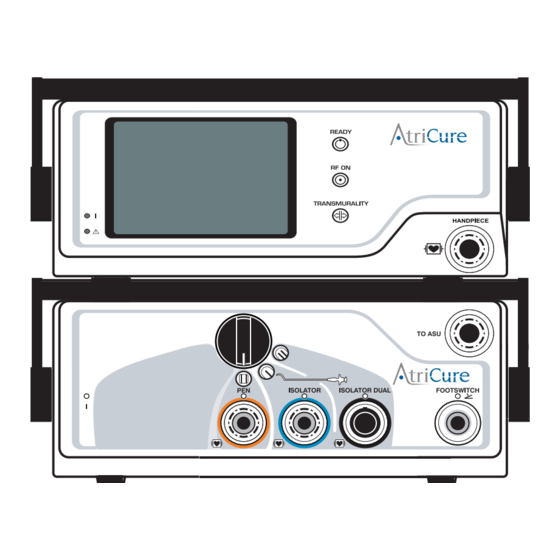
FRONT AND BACK PANEL CONNECTORS/CONTROLS FRONT PANEL CONNECTORS/CONTROLS Handpiece Receptacle The connection of the (Reusable, Non-Sterile) RF Interface Cable (A000442) between the Handpiece Receptacles on the front panel(s) of the ASU and ASB provides RF energy from the ASU to the Sterile Handpiece through the ASB�... - Page 16 Transmurality Indicator This LED indicator, when flashing Blue, indicates that the Transmurality TRANSMURALITY algorithm has been satisfied and that the user may terminate the ablation cycle� NOTE: This function is applicable only to the Synergy Clamps. ASU Power LED A green LED on the ASU front panel indicates the AC power is present, and the ASU has been switched ON�...
-
Page 17: Chapter 2 Setup And Operation
CHAPTER 2 SETUP AND OPERATION 5� Connect both the connectors into the Handpiece Receptacles on the front panel(s) of the ASU and ASB until a click is audible, the SETTING UP THE DEVICE connectors are keyed for alignment (refer to Figure 6: Connecting RF Interface Cable (ASU/ASB front panels))�... - Page 18 upward and oriented to the arrow symbol on the ASB receptacle (refer to Figure 4: ASU/ASB Front and Back Panel - Key Features), insert the sterile Handpiece(s) (Isolator Synergy Clamp or the Isolator Pen Handpiece) Cable connector(s) into the corresponding receptacle on the ASB Front panel� •...
-
Page 19: Device Operation
(Isolator Pens) indicating RF ON Mode (wrapping DEVICE OPERATION now shown))� 1� Position the Handpiece per the Handpiece IFU� 2� Press and hold the Footswitch to initiate RF energy output� RF energy output is terminated by releasing the Footswitch or at the end of 40 continuous seconds of energy delivery�... -
Page 20: Chapter 3 Preventive Maintenance And Cleaning
CHAPTER 3 PREVENTIVE MAINTENANCE AND CLEANING 2� If the unit or components are contaminated with blood or other body fluids, they shall be cleaned before the contamination can dry Follow local governing ordinances and recycling plans regarding the (within two hours of contamination)� disposal or recycling of device components�... -
Page 21: Chapter 4 Technical Specifications And Safety Inspection
CHAPTER 4 TECHNICAL SPECIFICATIONS AND SAFETY ELECTRICAL SPECIFICATIONS INSPECTION • ASU, rated: 100-120V ~ 50/60 Hz • ASB, rated: 100-240V ~ 50/60 Hz MECHANICAL SPECIFICATIONS ENVIRONMENTAL SPECIFICATIONS Size: ASU: 17�5” (44�5 cm) D x 13�75” (35 cm) W x 6” (15 cm) H maximum� Operating Conditions ASB: 17�5”... -
Page 22: No Rf Power Output
NO RF POWER OUTPUT Code E06 Switch Stuck Test Possible Cause Action Error: Footswitch Replace footswitch closed while ASU and/or ASB were not Turn power ON for ASU and/or ASB connecting turned ON Code E10 Handpiece ASU and/or ASB were not Confirm electrical connections for ASU Check electrodes or electrodes are... -
Page 23: Monitor (Display) Interference
PACEMAKER INTERFERENCE ERRORS during ASU Operation 1� Check all connections, Code F01 Illegal Cycle power OFF and back 2� Always monitor pacemaker patients during surgery� Instruction 3� Always keep a defibrillator available during electrosurgery on Code F02 Duplicate Variable If the problem persists, patients with pacemakers�... -
Page 24: Disclaimer
WARRANTIES Limitation on Liability This warranty and the rights and obligations hereunder shall be construed under and governed by the laws of the State of Ohio, U�S�A� AtriCure, Inc� warrants this product to be free from defects in material and workmanship under normal use and preventive maintenance for the respective warranty period shown below�...
Need help?
Do you have a question about the ASU2 and is the answer not in the manual?
Questions and answers