
Related Manuals for BRUEL & KJAER 3923


Summary of Contents for BRUEL & KJAER 3923
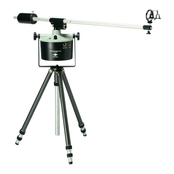
- Page 1 Rotating Microphone Boom Type 3923 From Serial number: 1913 432 Revision November 1996 Brüel & Kjær Rotating Microphone Boom Type 3923 BE 0165 –12 User Manual...
- Page 2 All rights reserved. No part of this publication may be reproduced or distributed in any form or by any means without prior consent in writing from Brüel & Kjær Sound & Vibration Measurement A/S, Nærum, Denmark. 0 − 0 Rotating Microphone Boom Type 3923 Brüel & Kjær User Manual...
-
Page 3: Table Of Contents
Use of the Sync. and Remote Control Socket ............2 – 7 Replacement of Drive Belts; Cam Removal or Installation ........2 – 7 3. Accessory Bag KF 0074 .................... 3 – 1 General......................... 3 – 2 0 − 3 BE 0165 –12 Rotating Microphone Boom Type 3923 User Manual... -
Page 5: Controls And Accessories
Chapter 1 Controls and Accessories BE 0165 –12 Rotating Microphone Boom Type 3923 1− 1 User Manual... -
Page 6: Controls
Accepts the B & K standard plug JP 0715. OUTPUT: Seven-pin plug for the connection of Type 3923 to B & K sound measurement instrumentation. The plug is connected, via 3 m cable and slip rings, to the PREAMP. INPUT socket. -
Page 7: Accessories
Set of spare drive belts. Replacement procedure is given in section 2.6. ZG 0283 Battery Charger for recharging the internal NiCd cells, Allows mains power operation of Type 3923 while recharging. See section 2.1. DV 0225: Cable clamps for firmly attaching the cable to the boom. - Page 8 1− 4 Rotating Microphone Boom Type 3923 Brüel & Kjær User Manual...
-
Page 9: Operation
Chapter 2 Operation BE 0165 –12 Rotating Microphone Boom Type 3923 2− 1 User Manual... -
Page 10: Power Supply
Type 3923. Fully-charged batteries allow 35 hours operation. Battery condition is monitored by the BATTERY METER. If the needle falls into the re area, the batter- ies should be recharged. This can be done in several ways, with Type 3923 in operation or not. See 2.1.2 Cells QB 0008 have a voltage and charge rating of 1.2 V and 4 Ah and may be... -
Page 11: Boom Assembly
3923 whilst simultaneously recharging the batteries. In this case, however, the bat- tery recharge time will be longer. It is also possible to use a DC voltage to operate Type 3923, and to recharge its internal NiCd batteries. To recharge the batteries and/or operate the instrument a voltage between 8.3 and 13 V is required. -
Page 12: Microphone Installation
DP 0217 should be fitted over the cable entry of the preamplifier (see Fig.2.2). Again, the Yokes should be adjusted to be parallel when the preamplifier and the Adaptor Ring have been fitted. 2− 4 Rotating Microphone Boom Type 3923 Brüel & Kjær User Manual... - Page 13 Chapter 2 — Operation Microphone Installation Fig.2.2 Half-inch Microphone and half-inch Preamplifier fitted to Suspension UA 0502 Fig.2.3 One-inch Microphone and half-inch Preamplifier fitted to Suspension UA 0502 BE 0165 –12 Rotating Microphone Boom Type 3923 2− 5 User Manual...
-
Page 14: Final Assembly
Care should be taken that the cable from Type 3923 does not introduce loading during the balance adjustment. 7. Connect the 7-pin plug of Type 3923 to the measuring instrumentation. 8. Connect the external power supply, if any (see section 2.1). -
Page 15: Use Of The Sync. And Remote Control Socket
6 the boom will continuously rotate. Replacement of Drive Belts; Cam Removal or Installation A spare set of drive belts is provided with Type 3923. When the belts are worn, they normally spring out of their pulleys, thus indicating the need for replacement. - Page 16 To gain access to the drive belts or to the cams, the procedure is as follows: 1. Turn the body upside down and remove the cover (see Fig.2.2). Fig.2.6 Type 3923 without cover 2. Disconnect the three connectors from the printed-circuit board and remove the board.
- Page 17 Chapter 2 — Operation Replacement of Drive Belts; Cam Removal or Installation Fig.2.7 Dismantled view of Type 3923 showing drive belts and cams 7. Fit the printed-circuit board in place and plug the connectors in. 8. Replace the cover over the body.
- Page 18 2− 10 Rotating Microphone Boom Type 3923 Brüel & Kjær User Manual...
-
Page 19: Accessory Bag Kf 0074
Chapter 3 Accessory Bag KF 0074 BE 0165 –12 Rotating Microphone Boom Type 3923 3− 1 User Manual... -
Page 20: General
Chapter 3 — Accessory Bag KF 0074 General General Accessory Bag KF 0074 is delivered as a standard accessory with Type 3923. Shows where the different accessories should be placed in the bag. Fig.3.1 Location of accessories in Bag KF 0074 3−...
Need help?
Do you have a question about the 3923 and is the answer not in the manual?
Questions and answers