Vmac VR70 Installation Manual
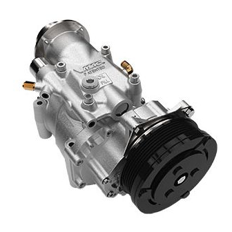
Underhood air compressor
Hide thumbs
Also See for VR70:
- Installation manual (80 pages) ,
- Owner's manual (48 pages) ,
- Information sheet (12 pages)
Table of Contents
Advertisement
Quick Links
UNDERHOOD AIR COMPRESSORS
UNDERHOOD AIR COMPRESSORS
UNDERHOOD AIR COMPRESSORS
UNDERHOOD AIR COMPRESSORS
UNDERHOOD AIR COMPRESSORS
UNDERHOOD AIR COMPRESSORS
UNDERHOOD AIR COMPRESSORS
UNDERHOOD AIR COMPRESSORS
UNDERHOOD AIR COMPRESSORS
UNDERHOOD AIR COMPRESSORS
UNDERHOOD AIR COMPRESSORS
UNDERHOOD AIR COMPRESSORS
UNDERHOOD AIR COMPRESSORS
1333 KIPP ROAD NANAIMO B.C. V9X 1R3
TEL: (250)-740-3200
FAX: (250)-740-3201
TOLL FREE: 800-738-8622
THE BENCHMARK IN INNOVATION
UNDERHOOD AIR COMPRESSORS
Installation Manual
System # V900019
1995 - 2001 INTERNATIONAL 4900,
4800, 4700, & 4700LP DT 466E
UNDERHOOD AIR COMPRESSORS
www.
underhoodair
TM
Visit us at...
.com
Advertisement
Table of Contents

Subscribe to Our Youtube Channel
Related Manuals for Vmac VR70


Summary of Contents for Vmac VR70
- Page 1 UNDERHOOD AIR COMPRESSORS Installation Manual UNDERHOOD AIR COMPRESSORS UNDERHOOD AIR COMPRESSORS UNDERHOOD AIR COMPRESSORS System # V900019 UNDERHOOD AIR COMPRESSORS 1995 - 2001 INTERNATIONAL 4900, 4800, 4700, & 4700LP DT 466E UNDERHOOD AIR COMPRESSORS UNDERHOOD AIR COMPRESSORS UNDERHOOD AIR COMPRESSORS UNDERHOOD AIR COMPRESSORS UNDERHOOD AIR COMPRESSORS UNDERHOOD AIR COMPRESSORS...
- Page 2 1930026- Illustrated parts list 1900130 - Warranty registration Registered Trademarks: VR70, VMAC and Throttle Commander are registered trademarks of VMAC. International is a trademark of Navistar International Corporation. Loctite, Klean N’ Prime, 242 and PST are registered trademarks of Loctite Corporation.
-
Page 3: Table Of Contents
Contents GENERAL INFORMATION ....................3 ........................5 NTRODUCTION ....................... 6 NSTALLATION OTES ........................7 RDERING ARTS ..........................7 ARRANTY ....................7 HANGES AND IMPROVEMENTS ....................8 PECIAL INSTALLATION NOTES PART 1: INSTALLING THE COMPRESSOR AND OIL COOLER ........ 9 1.1 P .................. -
Page 5: General Information
DOCUMENT 1930026 General Information System #V900019 1995 - 2001 INTERNATIONAL 4900, 4800, 4700, & 4700LP, DT 466E UNDERHOOD AIR COMPRESSOR... -
Page 7: Introduction
General Information Introduction This book provides installation instructions for: VMAC underhood air compressor installation kit VMAC Throttle Commander This kit has been designed for: 1995 - 2001 International 4900, 4800, 4700 & 4700LP, DT466E Installation steps The installation procedure in this manual has four main steps:... -
Page 8: Installation Notes
Installation Notes It is important that you complete all the installation steps before operating the system. Refer to the Owner’s Manual before operating the system for the first time. Follow all safety precautions for underhood mechanical work. Use Loctite 242 or equivalent on all engine-mounted fasteners. All hoses, tubes and wires which are re-routed or shifted during installation must be secured so that they do not contact excessively hot areas or sharp edges. -
Page 9: Ordering Parts
Please quote the VMAC part number, the description and the quantity. Warranty The VMAC warranty form is located at the back of this manual. This warranty form must be completed and mailed or faxed to VMAC at the time of installation for any subsequent warranty claim to be considered valid. -
Page 10: Special Installation Notes
(Figure 2). Failure to observe this procedure will result in damage to the system. The line from the VR70 tank to the auxiliary air receiver must have an auxiliary check valve installed to prevent blowback from the auxiliary tank and to prevent moisture from entering the VR70 tank. - Page 11 DOCUMENT 1930026 Part 1 Installing the Compressor Oil Cooler System #V900019 1995 - 2001 INTERNATIONAL 4900, 4800, 4700, & 4700LP, DT 466E UNDERHOOD AIR COMPRESSOR...
-
Page 13: Part 1: Installing The Compressor And Oil Cooler
Part 1: Installing the Compressor and Oil Cooler 1.1 Preparing for installation Remove the protective covers from the electrical connections on the engine management system located on the driver’s side of the engine. Remove the two hex head cap screws holding the electrical connectors on the engine management system and remove the electrical connectors from the unit. -
Page 14: Installing The Bracket And Compressor
Peen back the lip of the thermostat housing flush with the cylinder head. Clean all dirt and debris from the right side of the engine and fit the VR70 compressor mount bracket to the passenger side of the cylinder head (Figure 1.2 & 1.3). - Page 15 OEM fastener. Clean all dirt and residue from the inside of the harmonic balancer. Install the VR70 crank pulley using the six (6) supplied 10 x 45 mm fasteners. Use Loctite on the threads and torque the fasteners to specifications.
- Page 16 Install the VR70 belt. Figure 1.4 shows all of the belts, tensioners and idlers in place. Refit the 3/4 OEM heater supply hose to the 45 degree elbow angled down 15 degrees on the thermostat housing and tighten the clamp.
- Page 17 Fit the supplied fan spacer (left hand thread), then refit fan and fan shroud. Refit the coolant expansion bottle and hoses. Refit the 3/8 coolant expansion syphon hose to the hose barb on the thermostat housing. Route the hose away from the alternator pulley and secure.
- Page 18 Disconnect heater return hose and connect to front spigot on cooler. Cut to length 3/4 heater hose & fit from water pump to rear spigot on cooler Figure 1.7 Connect the 24 inch long 3/4” heater hose provided to the rear cooler 3/4 hose spigot then connect to the OEM fitting at the back of the engine water pump.
- Page 19 Figure 1.8...
- Page 21 DOCUMENT 1930026 Part 2 Installing the Air Tank and Lines System #V900019 1995 - 2001 INTERNATIONAL 4900, 4800, 4700, & 4700LP, DT 466E UNDERHOOD AIR COMPRESSOR...
-
Page 23: Part 2: Installing The Air Tank And Lines
If this is the case, measure the distance between the standard mounting position and the front of the tank in your application, then contact VMAC for replacement hoses. - Page 24 Figure 2.2 Figure 2.3...
- Page 25 Place the air tank into the brackets with the sight glass window toward the front of the truck. Install the retaining strap using a hex head cap screw, washers and Nylok nut through the top hole. Locate the tank as shown in Figures 2.4, 2.5 and 2.6. Figure 2.4 Make sure that the tank is sitting vertical as shown by the arrow on the rear of the tank before tightening the clamps (See figure 2.5)
-
Page 26: Connecting The Air And Oil Lines
2.2 Connecting the air and oil lines Install a hex head cap screw, washers and Nylok nut into the bottom hole on the strap. Repeat this procedure for the other bracket. Make sure that the rear tank bracket is positioned so that it does not clamp over the weld the back of the air tank. - Page 27 Figure 2.6 Tighten all system hoses securely to avoid any leaks. Fit the convoluted plastic loom to all hoses where they rub together or on the vehicle frame and components. Secure all the hoses together where possible, using plastic or steel ties provided. Use OEM fixtures if available. Avoid hoses rubbing on hot or sharp edges or surfaces.
-
Page 28: Adding Oil To The System
Make sure that the vehicle is level. Remove the oil fill plug from the inlet control valve and pour the 5 liters, (1.32 US gal.) of VMAC certified and approved supplied compressor oil into the fill hole on the inlet control valve using a funnel. - Page 29 DOCUMENT 1930026 Part 3 Installing the Control Unit System #V900019 1995-2001 INTERNATIONAL 4900, 4800, 4700, & 4700LP, DT 466E UNDERHOOD AIR COMPRESSOR...
-
Page 31: Part 3: Installing The Control Unit
Part 3: Installing the Control Unit 3.1 Installing the control unit Remove the screws holding the plastic protector panel in place on the floor inside the driver’s door. Remove the panel. Remove the rear seat rail bolt and fasten the bracket to the floor using the bolt through the rear-most hole (Figure 3.1) Mount the Controller Using These Holes... - Page 32 Figure 3.2 Figure 3.3...
- Page 33 Figure 3.4...
-
Page 34: Connecting The Wiring
3.2 Connecting the wiring Connect the two interface cable connectors. A wiring diagram is shown in Figure 3.4. Connect the green wire with the ring connector to a good ground (see Figure 3.6 for air brake systems). Route the red wire with the fuse holder under the dash to the fuse panel. Secure the wire as necessary using ties. - Page 35 3.3 Vehicles with air brakes Cut or drill a 3/4 inch hole in the plastic firewall connector where the air lines pass through the firewall (Figure 3.6). Be careful not to damage any lines or wires. Apply the spring brakes using the spring brake control on the dash of the truck. This will vent all air out of the spring brake chambers and lines.
- Page 36 Insert the ends of the lines in the T-fitting, slide the ferrules into position against the T-fitting and tighten the nuts. Start the engine and allow the air pressure in the air brake system to build up to cut-out pressure. Release the spring brakes using the control knob on the dash.
- Page 37 Figure 3.8 AIR BRAKES AND AUTOMATIC TRANSMISSION Solder or crimp the “VR70 black” wire on the Drive Disable Circuit, (DDC) to the black wire on the interface cable. Solder or crimp the “Park Brake Pressure Switch” jumper to the “Park Brake” black wire on the DDC.
- Page 38 Figure 3.10 Solder the blue DDC wire to the violet wire labeled “97A” as shown in Appendix A. VMAC recommends that all wire connections be soldered for reliability. A T-Tap connector has been supplied if this is not practical. NOTE 3.4 Hydraulic brakes...
- Page 39 Park brake connector Figure 3.11 3.4.1 Hydraulic brakes and Standard transmission PARK BRAKE INT ER FAC E T-TAP CON NECT ION CABLE SOLDER CON NECT ION PREFER ED OR 22- 18 T-TAP CON NECT ION CRIMP ON CRIMP ON BLACK WIRE OEM WIRE OEM W IRES (Test for selection - Pr obe each wire and m easure to Ground:...
- Page 40 Solder the black wire from the interface cable to the previously selected park brake wire. See Appendix A for soldering instructions. 3.4.2 Hydraulic brakes and automatic transmission Solder or crimp the “VR70 black” wire on the Drive Disable Circuit, (DDC) to the black wire on the interface cable. FIREWALL BULKHEAD...
- Page 41 Figure 3.15 Solder the blue DDC wire to the violet wire labeled “97A” as shown in Appendix A VMAC recommends that all wire connections be soldered for reliability. A T-Tap connector has been supplied if this is not practical. NOTE 3.5 Final testing and assembly...
- Page 42 Re apply the park brake. The green light should come back on. If the truck is an automatic, shift into gear. The green light should go off. Shift back to neutral. The green light should come back on. Turn off the control panel. Shift the transmission into gear. Turn on the control panel.
- Page 43 Appendix A - Soldering Instructions 1. Cut the OEM wire, and strip approx. 1/2” from each end and from the VR wire (Figure A1). Figure A1 2. Slide the heat shrink provided onto one OEM wire and the VR wire. Twist the 3 wires together (Figure A2).
- Page 45 DOCUMENT 1930026 Part 4 Installing the Throttle Commander System #V900019 1995 - 2001 INTERNATIONAL 4900, 4800, 4700, & 4700LP, DT 466E UNDERHOOD AIR COMPRESSOR...
-
Page 47: Part 4: Installing The Throttle Commander
Part 4: Installing the Throttle Commander 4.1 Mounting and connecting the Throttle Commander Mount the Throttle Commander on an available hole in an OEM bracket under the dash, using the supplied fastener (Figure 4.1). Tighten the fastener. Figure 4.1... - Page 48 Before operating this system for the first time, read the information, precautions and instructions in the VR70 Owner’s Manual. NOTE Be sure that the engine oil level is at the correct level, the oil filter does not leak and that the engine coolant level is correct.
-
Page 49: Illustrated Parts List
PART 4 ILLUSTRATED PARTS LIST SYSTEM #V900019 1995-2001 INTERNATIONAL 4900, 4800, 4700, & 4700LP, DT 466E... - Page 50 Document #1930026...
- Page 52 ILLUSTRATED PARTS LIST FOR SYSTEM V900019 - 1995-2001 INTERNATIONAL 4900, 4800, 4700 & 4700LP. DT 466E ASSY.ITEM UNIT PART# DESCRIPTION 4800274 Main Bracket Assembly 1100126 VR70 main bracket 3300021 Tensioner 1570048 Washer 1/2 inch SAE 1520419 12mm × 80mm G10.9 HHCS 3400023 Fan spacer...
- Page 53 3.10 5000089 3/8 inch NPT – 1/2 inch SAE Brass connector 3.11 3200227 Ring, window 3.12 9200039 VR70 oil filter 3.13 3600054 200PSI Relief valve 3.14 4900033 3/4 inch NPT × 3/4 inch 37 Deg JIC steel connector 3.15 5830008 O-Ring, Vitron, 1-15/16 inch ID 3.16...
- Page 54 ILLUSTRATED PARTS LIST FOR SYSTEM V900019 - 1995-2001 INTERNATIONAL 4900, 4800, 4700 & 4700LP. DT 466E ASSY.ITEM UNIT PART# DESCRIPTION Throttle Control Assembly 3620043 VR70 Throttle control, Mechanical 3550388 Control box 3550393 Interface cable 4800161 Switch, air brake pressure 3550661 DDC, 2001 International 4700/4900 DT466E ASSY.ITEM...
Need help?
Do you have a question about the VR70 and is the answer not in the manual?
Questions and answers