
Related Manuals for ELINTA CHARGE CityCharge V2

Summary of Contents for ELINTA CHARGE CityCharge V2
- Page 1 Public Electric Vehicle Charging station CityCharge V2 Installation Manual Elinta Charge, UAB | Partizanu g. 63M, Kaunas 50306, Lithuania | www.elintacharge.com...
- Page 2 No portion of these materials may be duplicated, used or disclosed without prior written permission from Elinta Charge, UAB Disclaimer: This installation manual includes the latest information available at the time of printing. Elinta Charge, UAB reserves the right to make changes to this installation manual and/or product without further notice.
-
Page 3: Table Of Contents
Contents INTRODUCTION ............................5 Purpose of the Manual ......................6 Qualified Personnel ........................ 6 Symbol Usage ......................... 6 High Voltage Warning ......................7 Important Safety Instruc ons ....................7 Addi onal Safety Informa on ....................8 Repair and Maintenance Clause ..................... 8 Defini ons.......................... - Page 4 SETTINGS AND TESTING........................44 RCD Type B (op onal) ......................45 RCD Type A and Type B Tes ng .................... 46 Dynamic Load Management Setup online (op onal) ............47 Payment Solu on Using The Payter (op onal) ..............49 Se ng Up The Price Rules For Payter .................
-
Page 5: Introduction
Chapter 1 INTRODUCTION... -
Page 6: Purpose Of The Manual
Purpose of the Manual This manual provides information about the installation process of the public charging station CityCharge V2. This document is designed for engineers and electricians who possess a general knowledge of electrical installation. Qualified Personnel The product described in this document may be installed only by... -
Page 7: High Voltage Warning
It is recommended that your CityCharge V2 be installed by a licensed electrician. To avoid serious injury or death, in- stallation must be in accordance with the manufacturer's installation instructions and comply with all local codes. -
Page 8: Addi Onal Safety Informa On
Please refer to your vehicle owner's manual for ventilation requirements. Repair and Maintenance Clause Elinta Charge products: CityCharge V2 do not require rou- tine maintenance, however, periodic inspections should be conducted to ensure that all parts remain in good working order and no damage exists. -
Page 9: Defini Ons
Definitions (Alternating Current): A charge of electricity that regularly AC - changes direction. (Alternating Current): A charge of electricity that regularly kW - changes direction. The strength of an electric current measured in amperes or A / mA - milliamperes A unit of energy equivalent to the energy transferred in one hour by one thousand watts of power. -
Page 10: Moving, Transpor Ng And Storage Instruc Ons
Moving, Transporting and Storage instructions It is recommended to store the charging station indoors and in a non-humid environment, keeping it in its original packag- ing until it is ready to be installed. Storage temperature should be between -30 °C and +60 °C When moving or lifting the unit, always carry the unit by the enclosure, never attempt to lift, move, or carry the unit alone. -
Page 11: Preparation
Chapter 2 PREPARATION... -
Page 12: Site Selec On
Site Selection Selecting a site for EVSE installation will likely require consideration of a combination of factors. While every site is unique and every EVSE host has priorities for installation, common physical elements characterize every EVSE site design. Some of the most common design elements to look for: Power Rating of Charging Station Proximity to Power Distribution Box... - Page 13 Power Rating of Charging Station - Connecting the charging station to a power source will require the evaluation of existing electrical capacity. Sometimes greater power charging stations are unnecessary for the selected location. Such as workplac- es, where people tend to stay the whole workday and bigger power charging stations will not be beneficiating between charging station power and electrical system power, consider two parts: the electrical system at the location of the EVSE in-...
- Page 14 Available Network Communications - Charging stations are much more with internet communication: mobile phone apps, payment solutions, charging reservations - all these functions are available with internet connectivity. When choosing a location for the charging station: make sure there is the possibility to share a network with the charging station. Charging stations usually accept all common communication types: Wi-Fi, LAN or GSM/4G.
-
Page 15: Installation
Chapter 3 INSTALLATION... -
Page 16: Charging Sta On Overview
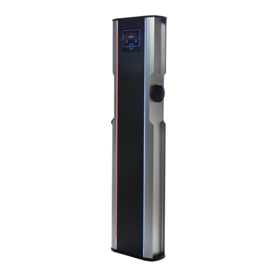
Charging Station Overview CityCharge V2 is classified as a fast Mode 3 charging station with the ability to provide up to 44 kW (2x22 kW) of power using two Type 2 charging sockets. The bright animated LED screen and sidebars are visible even in the direct sunlight. -
Page 17: Charging Sta On Specifica Ons
Charging Station Specifications Charging Station CityCharge V2 technical specification: Weight: 35 kg Dimensions: 150 x 350 x 1370 mm Phase Count: 3 Operating Voltage: 400 V/AC Maximum Power: 44 kW Impact protection rating: IK10 IP class: IP54 Temperature range: -30 °C to +50 °... -
Page 18: Charger Internal Components (Standard)
Charger Internal Components (Standard) MainBoard Thermostat For Heater Electronics Power Communication Modem Supply Payment Terminal Cable Lock Actuator LED connector Charge Controllers Smart Energy Meters Side A Circuit Breaker Side B Circuit Breaker Power Contactors MainBoard Circuit Breaker RCD Side A RCD Side B Heater Element Wire Terminals... -
Page 19: Charger Internal Components (With Automa C Rcd Trip Reset)
Charger Internal Components (With Automatic RCD Trip Reset) MainBoard Thermostat For Heater Electronics Power Communication Modem Supply Payment Terminal Cable Lock Actuator LED connector Charge Controllers Smart Energy Meters Side A Circuit Breaker Side B Circuit Breaker Power Contactors MainBoard Circuit Breaker RCD Side A RCD Side B RCD Trip B Reset... -
Page 21: Tools And Consumables For Installa On
Tools and Consumables For Installation We recommend that you have these tools and consumables ready before you start installing the charging station: Consumables: 7-8 bags of concrete mixture · Water · Tools needed: Shovel · Concrete mixer · 18 mm wrench ·... - Page 22 Concreting The Mounting Pad The mounting plate should be set in concrete with a longer threaded side facing the ground. The power supply cable must be led out through the hole Mounting Pad in the middle of the base. The power supply cable must protrude at least 40 cm from the base of the Mounting Pad.
- Page 23 Note: The mounting pad should be flush with the ground. If the installation is taking place on brick tiles, then the mount- ing pad should be flush with the top of the brick tile. See in- stallation examples below:...
-
Page 24: Power Supply Cable Introduc On
Power Supply Cable Introduction The power supply cable must be run to the bottom of the hole. The cable should be protected by the corrugated PVC pipe. The diameter of the pipe should not exceed 100 mm. Ensure that both the corrugated PVC pipe and the power supply cables are perpendicular to the mounting surface. -
Page 25: Charging Sta On Unpacking
After removing the charging station from the packaging, keep the card- board box for the entire warranty period in case the charging station needs to be sent in for repair. Standard package includes: Charging Station CityCharge V2 - 1 pcs. · Mounting metal pad - 1 pcs. ·... -
Page 26: Charging Sta On Installa On
3.12 Charging Station Installation 1. Remove the charging station from the packaging and place it vertically on a smooth, flat surface. 2. Open the service doors of the charging station by opening the two locks on the back of the charging sta- tion. - Page 27 5. Lift up the service doors from the charger. 6. Lean the charger service door against the charging station , while the installation is taking place 7. Loosen the nuts from the charging station bracket with an 18 mm wrench. 8.
- Page 28 10. Tighten down x4 bolts using an 18 mm wrench. Use the tightening force of 60 Nm. 11. If the charging station appears slightly vertically or horizon- tally skewed, it is possible to level out the charging station by using stainless steel washers between the charging station and the mounting pad.
-
Page 29: Power Supply Connec On
3.13 Power Supply Connection Be sure to follow the electrical installation instructions. Failure to do so may result in damage to the unit or personal injury. This charging station has been designed for operation with the power supply systems TNC-S; TNS or TT. Make sure that the ground resistance is not greater than 10 Ω. - Page 30 Recommended calculated values for CityCharge V2 charging station wires: (When calculated cable length Max: 50 meters; Power factor (cosφ): 0,95; voltage drop (%): 7%; Cabling method: Four single core copper wire in the pipe (three phase)): Side A, Power Side B, Power...
- Page 31 Danger: Before connecting the power cable, make sure that no current flows through the cable Power Supply. TN 3-phase connection to the grid: L1 L2 For TN 3-Phase: connect Power Supply Cable three phases L1; L2; L3 to three separate wire terminals. (Grey color wire termi- nal) Connect the Power Supply Cable neutral (N) to the blue wire terminal.
- Page 32 TN 1-phase connection to the grid: For TN 1-Phase: connect Power Supply L1 to the Grey color wire terminal. Connect the Power Supply Cable neutral (N) to the blue wire terminal. Connect the Power Supply Cable Earth wire (PE) to the green- yellow wire terminal.
- Page 33 IT 3-phase connection to the grid: L1 L2 For TN 3-Phase: connect L1 to charger’s Phase 1. Connect L2 to charger’s Phase 2. Connect L3 to charger’s Neutral. Connect the Power Supply Cable Earth wire (PE) to the green-yellow wire terminal. IT 1-phase connection to the grid: For TN 1-Phase: connect L1 to charger’s Phase 1.
-
Page 34: Lan Cable Connec On (Op Onal)
3.14 LAN Cable Connection (optional) Danger: Before connecting the LAN cable, make sure that no current flows through the cable Power Supply. If the CityCharge V2 charging sta- tion is equipped with a LAN option, make sure you follow these proce- dures to route the cable correctly in the charging station. -
Page 35: Gsm Modem Se Ngs And Setup (Op Onal)
LAN, Wi-Fi, GSM/3G/4G. The charging station can be in- stalled in a remote place and has a good communication speed via mobile network GSM/3G/4G communication. If CityCharge v2 with GSM/3G/4G option is selected, the additional equipment will be installed in the charging station: Modem Teltonika RUT240:... - Page 36 To set up the station for operation with GSM/3G/4G communication, the SIM card must be inserted into the modem: Using sharp object push SIM card tray release button. Take out the SIM card tray. Put the SIM card into the tray. Push SIM card tray into the modem.
-
Page 37: Alterna Ve Lan Connec On
WAN LED should light up and start flashing, indicating that communica- tion has started. DO NOT press the "reset button" on the modem. CityCharge V2 is shipped fully configured for use. Pressing the "Reset" button will erase all configuration settings. -
Page 38: Dynamic Load Management Wiring (Op Onal)
3.17 Dynamic Load Management Wiring (optional) Danger: Before connecting the Dy- namic Load Management UTP cable, make sure that no power is flowing through the Power Supply cable. Turn off the power to the Charging Station Dynamic Load Management (DLM) requires additional wiring between the smart energy meter and the charging station. -
Page 39: Initial Startup
Chapter 4 INITIAL STARTUP... -
Page 40: First Time Start-Up
First Time Start-UP STEP 1: Turn on both A and B side residual current circuit breakers. STEP 2: Turn on both A and B side circuit breakers. STEP 3: Turn on electronics circuit breaker. STEP 4: Closer service doors. STEP 5: Wait at least 5-10 min. for charger to boot-up. STEP 2 STEP 1 STEP 3... -
Page 41: Charger Boot Sequence
Charger Boot Sequence Charging station CityCharge V2 The first start-up can take up to 10 min. After turning on the charging station, leave it on. Do not turn off the charging station until the charger screen displays the message "Ready". There is a possibility that the charging station is initiating a software update process, which can be disrupted by switching it off immediately. - Page 42 When the charging station decides to download the latest software version, the blue circle will "run in circles" until the download and in- stallation process is complete. Usually, this process takes after a re- boot or power failure. Normally, this step is skipped during the first boot-up.
- Page 43 After these steps, the charging station should glow a constant color. The charging station screen will display "Ready". At this point, it is possible to use the charging station to charge the EV. Plug the charging cable into the charging station and the other end into the electric vehicle.
-
Page 44: Settings And Testing
Chapter 5 SETTINGS AND TESTING... -
Page 45: Rcd Type B (Op Onal)
RCD Type B (optional) By default, CityCharge V2 is provided with residual current circuit breakers type A. This RCD type A ensures: The control and isolation of circuits. · The protection of people against direct and indirect contact. · The protection of installations against insulation faults ·... -
Page 46: Rcd Type A And Type B Tes Ng
RCD Type A and Type B Testing The CityCharge V2 charging station is always supplied with two residual current circuit breakers (RCD), which should be tested every 3 months of use. To test the RCD, follow these steps: Stop all car charging. -
Page 47: Dynamic Load Management Setup Online (Op Onal)
Dynamic Load Management Setup online (optional) Log in to your administrative elios.cloud website: Go to the Stations tab. Select the station whose power you want to regulate. Go to the Edit tab. At the bottom of the page, configure these settings: Balance Mode - how charger balances power: If selected: None - the charger does not balance between its sockets, but maintains the current on fixed value. - Page 48 Max current (Socket) – maximum amperage provided to the socket Max current (Dynamic input) – power input circuit breaker’s nominal current. Max current (Dynamic reserve) – reserve current left for buildings ap- pliances Max current (Dynamic capacity) – Total amperage available for the chargers In this example, the charging station may use the power that: Building power (32 A) - Dynamic reserve (13 A) = max.
-
Page 49: Payment Solu On Using The Payter (Op Onal)
Payment Solution Using The Payter (optional) CityCharge V2 charging stations can accept payments in two ways: Via the ElintaCharge app using a credit card. · With the Payter contactless payment terminal. · The CityCharge V2 can be selected with a... - Page 50 Using The Payter Payment Terminal LED indicators Status DisplayBlue Backlight Contactless Symbol Triangle Button To start charging: connect the EV to the charging station. Take your contactless payment card and place it on the contactless symbol (3). The LED indicator (1) will light up and a beep will be heard. Remove the contactless card from the reader.
-
Page 51: Se Ng Up The Price Rules For Payter
Setting Up The Price Rules For Payter To set up the price for the charging service, you need to set the price parameters: Open the web browser and go to: elios.cloud. Log in to the Elios platform with your username and password. Navigate to the "Stations"... - Page 52 The payment tab will open with all available settings for the price setting: Currency - The currency in which the client will be charged. Initial price - The price which the client will be charged just for con- necting to the charging station. Price per minute - The cost of each minute spent charging.
- Page 53 Save the changed settings with the "Save to this" button or alter- natively, if you want to save the same settings for all chargers in the same group, with the "Save to group" button. Lastly, the charging station needs to be set as "paid" so it can use the settings you made earlier.
-
Page 54: Troubleshooting
Chapter 6 TROUBLESHOOTING... - Page 55 The table below lists the most common solutions to problems: Charging sta on CityCharge V2 Troubleshoo ng Table Problem Possible cause Troubleshoo ng Charging sta on not func- No power to charg- Open charging station oning. Screen shows noth- ing sta on. Or RCD / service doors.
- Page 56 Charging sta on CityCharge V2 Troubleshoo ng Table Problem Possible cause Troubleshoo ng The charging sta on keeps Bad signal/ Depends on the selected losing a connec on to the connec on. communication. The server. problem could be a poor signal from WiFi or GSM.
-
Page 57: Warranty
Chapter 7 WARRANTY... -
Page 58: Warranty Rules And Condi Ons
All non-functioning chargers (or parts) are considered the property of Elinta Charge and must be returned to Elinta Charge when re- placement chargers (or parts) come in for replacement. The warranty is valid when installed by a certified electrician who has installed the charger in accordance with these installation in- structions. -
Page 59: Not Included Into The Warranty
Contact the technical service Elinta Charge, tel. +370 653 66633 or +370 615 71604 or support@elintacharge.com. When registering a fault, have the serial number of the charg- ing station, the device name, and a detailed description of the fault ready. -
Page 60: Final Thoughts
If you have any questions about the use or installation of the charging station, please contact the company that installed the unit or the technical support department of Elinta Charge. This document does not limit the rights of the consumer to the warranty if the purchased product (device) is of poor quality.
Need help?
Do you have a question about the CityCharge V2 and is the answer not in the manual?
Questions and answers