Table of Contents
Advertisement
Quick Links
Advertisement
Table of Contents

Related Manuals for Fencee MX10

Summary of Contents for Fencee MX10
- Page 1 Electric fencing User manual REMOTE MONITORING OF FENCE PARAMETERS WORKS ONLY WITH: Wireless RF connection with the Gateway. IT DOES NOT NEED A SIM CARD No additional operating costs. www.fencee.eu www.fenceefarm.com fencee Cloud To download +420 730 893 828...
-
Page 2: Table Of Contents
Thank you for purchasing the MX10 Monitor from VNT electronics s.r.o. The device complies with the safety regulations according to the valid law as well as the relevant EU regulation (CE). The device complies with the Council of Europe Directive 2014/53/EC, meets the requirements of the General License of the Czech Telecommunication Office according to the general authorization No. -
Page 3: Introduction
• Power battery: 2 × C-LR14 • Dimensions: 78 × 144 × 42 mm • Weight: 370 g 4. PACKAGE CONTENTS • MX10 Monitor • Two C-LR14 batteries • Magnet with a string • Earthing pin • Earthing cable for grounding •... -
Page 4: Description Of The Device
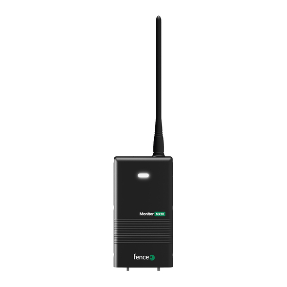
5. DESCRIPTION OF THE DEVICE • The Monitor MX10 is used to measure voltage anywhere in your fence system. • Up to 12 MX Control Monitors can be pair to a Gateway and divided the enclosure into multiple zones. Everything then communicates with the central Gateway and the... - Page 5 Inserting the batteries • Unscrew the screws and open the cover on the back of the Monitor. • Insert two C-LR14 batteries according to the instructions in the plastic cover. • Return the cover to its original position and tighten the screws firmly. An opening for the cable tie 2 ×...
-
Page 6: Description Of Controls
Control The device is controlled by the included magnet, which must be attached to the target on the side of the MX10 Monitor. When the magnet approaches, the status of the Monitor is indicated by an LED diode: Red = off Green = on If no LEDs light up, the batteries need to be checked and replaced. -
Page 7: Pairing The Monitor With The Gateway
7. PAIRING THE MONITOR WITH THE GATEWAY First, the MX10 Monitor must be paired with the Gateway in order to display the measured data. Pairing is performed by the following steps: The Monitor must be turned off. The LED flashes red. -
Page 8: Connection With Gateway
8. CONNECTION WITH GATEWAY Monitor measures each pulse in the fence system and sends the values to the Gateway every 15 minutes. If a voltage lower than the set limit is measured , data is sent to the Gateway immediately and an alarm is triggered. Setting the low voltage alarm level on the fence system The 3 kV limit is set at the factory. -
Page 9: Installing The Monitor On A Fence
9. INSTALLING THE MONITOR ON A FENCE After pairing the Monitor with the Gateway, it is possible to place the Monitor in the desired location of measurement on the fence system. Before installation, it is necessary to turn off the energizer, in order to ensure safe handling. We install the Monitor as shown in figure. - Page 10 Installation examples Put the monitor in the key sections where voltage needs to be checked (fence entrance) or where frequent problems, TIP: for example, with vegetation, by the forest, by the water, or when disconnected fence gate, can be expected. Standard installation Fence divided into sections.
- Page 11 For fence entrances Installation for quick identification of the fence with a non-functional energizer. Control installation for closing a gate The monitor can also be installed on the gate insulator eye. If the handle hook is disconnected and the eye lacks voltage, the monitor evaluates the situation and sends an alarm to the gateway.
- Page 12 MODERN SMART FARM SYSTEM WORKS ONLY IN CONJUNCTION WITH RF ENERGIZERS: fencee power DUO RF PDX fencee energy DUO RF EDX AND A CENTRAL CONTROL DEVICE: FENCE WiFi GATEWAY GW100 FENCE GATEWAY GW10 RF ENERGIZER Energizer External alarm High-voltage connecting cable...
- Page 13 Cloud External Antenna GATEWAY GW100 RF ENERGIZER Monitor MX10 Tensioner Gate handle Insulators Insulator of gate Warning sign...
-
Page 14: Troubleshooting - Possible Fault Sources
10. TROUBLESHOOTING - POSSIBLE FAULT SOURCES Cause Troubleshooting Pairing cannot be completed The surroundings is very noisy, or the signal between the Monitor and the Gateway is too weak. Try pairing the device with antennas closer to each other or in less noisy environment. - Page 15 Get insights with fencee Cloud Control and monitor your fences from your mobile phone, tablet or computer. THANKS TO THE REMOTE CONTROL, YOU DON‘T HAVE TO GO AROUND THE FENCES ANYMORE WELL - ARRANGED CURRENT ONLINE GRAPHS INFO ALARMS LIST OF...
- Page 16 20022023 Electric fencing Seller‘s stamp and signature: Smart Farm fencee Cloud System is protected in the EU utility model. VNT electronics s.r.o. Dvorská 605, 563 01 Lanškroun Czech Republic www.fencee.eu info@fencee.eu +420 730 893 828 www.fenceefarm.com www.fenceecloud.com fencee.cz fenceeczech...
Need help?
Do you have a question about the MX10 and is the answer not in the manual?
Questions and answers