
Related Manuals for Rice Lake ISHIDA WIL-Acro II


Summary of Contents for Rice Lake ISHIDA WIL-Acro II
- Page 1 WIL-Acro II Compact Label Printer with Color Touchscreen Service Manual: Technical ISHIDA RICEL�l<E. January 26, 2023 PN 217886 Rev A RETAIL SOLUTIONS...
- Page 2 Introduction • Purpose of this Manual The purpose of this manual is as reference material for the delivery, installation, repair and maintenance of this machine. • Target Readers This manual has been written specifically for use by our service personnel. The use of this manual by any person other than the above is strictly prohibited.
-
Page 4: Table Of Contents
Table of Contents Chapter 1 Overview ................... 4 1 .1 Name of Each Part ....................... 4 Specifications ....................... 5 Features ........................6 Chapter 2 Electrical ................... 7 Placement of Each Electrical Component ..............7 Electrical Block Diagram ....................9 Printed Circuit Boards ....................1 O 2.3.1 Main Board: PWB'P-1100'B (PN 158280) ............ -
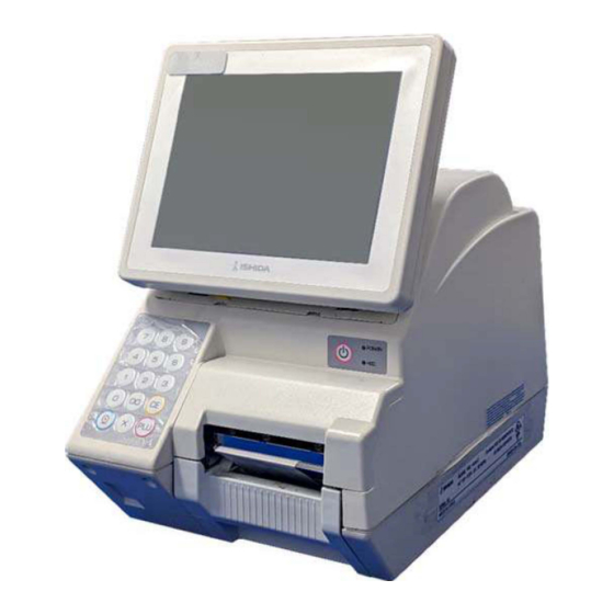
Page 5: Chapter 1 Overview
Chapter 1 Overview 1. 1 Name of Each Part Operation unit (8.4-inch TFT Touch panel) Stroke keys Thermal head LED power lamp LED memory access lamp Cassette Main power switch Connector cover LAN (Ethernet) USB x 2ch USB x 4ch Connector for Cash drawer (option) -
Page 6: Specifications
Specifications Item Content Machine name WIL-Acroll ° Operating environment Temperature: 0 to 35 Humidity: 20 to 80% (non-condensing) * Printable environment depends on label specifications. External dimensions 226 (W) x 370 (D) x 360 (H) mm Weioht 11 ko Power supply 100VAC ±10%, 50/60 Hz Insect-proof measures Use of cockroach repellent... -
Page 7: Features
Features QR codes can be printed. Electricity 1. 8.4-inch color TFT LCD is used for the store-side display (800 x 600 dots: SVGA) 2. The printing speed is faster (max. 150 mm/sec for high-sensitivity labels) 3. PC standard general-purpose USB port (Ver. 2.0) is provided Mechanism 1. -
Page 8: Chapter 2 Electrical
Chapter 2 Electrical Placement of Each Electrical Component a. LCD connector board (P-1033) b. Thermal head, label gap sensor c. Peel sensor d. Cassette sensor e. Switch power supply unit... -
Page 11: Printed Circuit Boards
Printed Circuit Boards 2.3.1 Main Board: PWB'P-1100B (PN 158280) - Page 13 DIPSW The above photo shows that only switch position 1 is in the ON state. SW No. Setup Remarks Four-wire touch panel 2 OFF Battery Jumper The battery jumper should be at the ON position (down) when viewed from the direction in the first photo. (The side where ON is silk-printed on the board) When shipped as a replacement board, the battery jumper is set to OFF, so move the jumper to ON when the board is in stalled.
-
Page 14: Power Switch Board: Pwb'p-984'-1(Pn 158263)
2.3.2 Power Switch Board: PWB'P-984'-1 (PN 158263) Connector No. Other end Main board, XJ23 2.3.3 LCD Junction Board: PWB'P-985' (PN 87519) Connector No. Other end Remarks Fasten terminal Shielded line P-1033, XJ2 Touch panel XJ100 Fasten terminal Shielded line XJ101 Main Board, XJ22 Touch panel XJ102 Main Board, XJ9... -
Page 15: Numeric Keypad Board: Pwb'p-944'-1 (Pn 185572)
2.3.4 Numeric Keypad Board: PWB'P-944'-1 (PN 185572) Connector No. Other end Remarks Main board, XJ22 2.3.5 Touch Panel Relay Board: PWB'P-1033' (PN 198416) Connector No. Other end Remarks Touch panel LCD junction board,... -
Page 16: Wireless Lan Board: Pwb'pk-265'B(Pn 119158)
2.3.6 Wireless LAN Board: PWB'PK-265'8 (PN 119158) Connector No. Other end Remarks Main board, XJ25 Wireless LAN module power su oo l v Main board... -
Page 18: Removing Controller Unit, Printer Cover, And Body Case
"3.8 Replacing the Main Board" "3.9 Replacing the Switch Power Supply (DL912W)" k. "3.6 Replacing the Fan" Removing Controller Unit, Printer Cover, and Body Case This section describes the procedures for removing the controller unit, printer cover, and body case. 3.2.1 Removing the Controller Unit When disassembling this machine, be sure to unplug the power plug from the... -
Page 19: Removing The Printer Cover
@ Remove the four screws securing the hinge. NOTE Remove the horizontal screws first, then remove the vertical screws while supporting the controller unit so that it does not topple. The cable is connected to the controller unit. Be careful not to disconnect the cable. @ Disconnect the wires connected to the main body. -
Page 20: Removing The Body Case
Remove the right side of the printer cover by pushing the right side inward while lifting the front of the cover. NOTE Be careful not to scratch the printer cover by letting the cover come in contact with the rinter bracket. of the printer cover. -
Page 22: Replacing And Repositioning The Thermal Head
Replacing and Repositioning the Thermal Head 3.3.1 Replacing the Thermal Head * Be sure to remove the printer cover beforehand in accordance with the procedure described in "3.2.2 Removing the Printer Cover". CD Pull out the head section. ® Lift the thermal head section with both hands to compress the springs and pull it toward you. -
Page 23: Adjusting The Thermal Head Position
3.3.2 Adjusting the Thermal Head Position CD Take out the cassette. ® Check if each of the following gaps are in the state shown below, and if not, adjust them. Gap between the guide lever and label width (paper tube) of the label receiving section: 0.2 to 1 mm Gap between the label guide and the liner: 0.1 to 0.4 mm... -
Page 25: Replacing The Label Gap Sensor
Replacing the Label Gap Sensor * Be sure to remove the printer cover beforehand in accordance with the procedure described in "3.2.2 Removing the Printer Cover". CD Pull out the head section. ® Remove the bracket. Screw: 2 places NOTE •... -
Page 26: Replacing The Peel Sensors
@ Make sure that the label gap sensor is securely attached. NOTE Check that the sensor surface is flush with the sheet metal surface. Replacing the Peel Sensors CD Take out the cassette. @ Remove the peel sensor (right side). Screw: 1 place Connector: 1 place NOTE... -
Page 27: Replacing The Fan
Replacing the Fan * Be sure to remove the body case beforehand in accordance with the procedure described in "3.2.3 Removing the Body Case". CD Remove the bracket. Screw (a): 2 places @ Disconnect the fan connector on the main board. -
Page 28: Replacing The Wireless Lan Board
3. 7 Replacing the Wireless LAN Board * Be sure to remove the body case beforehand in accordance with the procedure described in "3.2.3 Removing the Body Case". CD Remove the connector cover plate. Screw (a): 2 places @ Remove the wireless LAN board. Screw (b): 2 places Connector: 1 place @ After replacement, install each part in the... -
Page 29: Replacing The Main Board And Downloading Firmware
Replacing the Main Board and Downloading Firmware ■ Main board replacement P-1100, the main board of WIL-Acroll, is designed to operate with the OS and applications placed in the flash ROM of the CF. Downloading EC and FPGA applications to the flash ROM of the P-1100 enables operation of printers and board-to-board communication. -
Page 30: Replacement Of Main Board (P-1100)
3.8.1 Replacement of Main Board (P-1100) * Be sure to remove the wireless LAN board beforehand in accordance with steps 1) and 2) of "3.7 Replacing the Wireless LAN Board". CD Disconnect all connectors and remove the main board. Screw (c): 4 places [CF (XJ10)] Transfer the CF(CompactFlash) from the original board to the replacement board. -
Page 32: Downloading Firmware For P-1100 Board After Board Replacement
3.8.2 Downloading Firmware for P-1100 Board after Board Replacement NOTE "EC" and "FPGA" cannot be downloaded at the same time. Download the applications one by one. CD Remove the CF (CompactFlash) from the old board and insert it into the new board. ®... -
Page 36: Replacing The Cf (Compact Flash) Card
3.8.3 Replacing the CF (Compact Flash) Card... -
Page 37: Replacing The Switch Power Supply Unit
Replacing the Switch Power Supply Unit * Be sure to remove the body case beforehand in accordance with the procedure described in "3.2.3 Removing the Body Case". CD Unscrew the base so that it can be shifted. Screw (a): 3 places Screw (b): 1 place ®... -
Page 38: Replacing The Cassette Sensor
3.10 Replacing the Cassette Sensor * Be sure to remove the switch power supply unit beforehand in accordance with steps 1) to 3) of "3.9 Replacing the Switch Power Supply Unit". CD Take out the cassette. ® Remove the sensor mounting screws. Screw: 2 places @ Disconnect the cables from the clamp on the power supply unit side. -
Page 39: Replacing The Electrical Components In The Controller Unit
3.11 Replacing the Electrical Components in the Controller Unit * Be sure to remove the controller unit beforehand in accordance with the procedure described in "3.2.1 Removing the Controller Unit". CD Remove the hinge torque. Screw: 2 screws each @ Remove the rear cover. Screw: 6 places @ Remove the harnesses and screws and replace each board as appropriate. -
Page 40: Consumable Parts/ Periodic Replacement Parts
3.12 Consumable Parts/ Periodic Replacement Parts ■ Consumable parts Part Name Ishida Genuine Part Replacement Cycle (aooroximate) Thermal head 3-inch 30 to 60 km A "+" driver is required to remove the thermal head from the mountinq bracket. - Page 42 RETAIL SOLUTIONS © Rice Lake Weighing Systems Content subject to change without notice. 230 W. Coleman St. • Rice Lake, WI 54868 • USA U.S. 800-472-6703 • Canada/Mexico 800-321-6703 • International 715-234-9171 • Europe +31 (0)26 472 1319 www.ricelake.com PN 217886 Rev A...
Need help?
Do you have a question about the ISHIDA WIL-Acro II and is the answer not in the manual?
Questions and answers