Table of Contents
Advertisement
Quick Links
Advertisement
Table of Contents

Related Manuals for Japan Radio Co. JFE-380


Summary of Contents for Japan Radio Co. JFE-380
- Page 1 JFE-380 JFE-380 Echo Sounder Echo Sounder INSTRUCTION INSTRUCTION MANUAL MANUAL...
- Page 2 edition...
-
Page 3: General Information
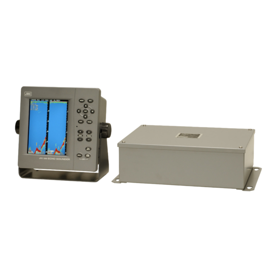
General Information Thank you for purchasing the Japan Radio Co., Ltd. JFE-380 Echo-Sounder. The JFE-380 conforms to the IMO (International Maritime Organization) performance standards, enabling seabed displays and digital depth displays. Before attempting to operate this equipment, read this instruction manual thoroughly to ensure correct and safe operation in accordance with the warning instructions and operation procedures. - Page 4 edition General Information ii...
- Page 5 Before You Begin Symbols Used In This Manual To ensure that the equipment is used safely and correctly, and that the operator and third parties are not exposed to danger or damage, pictograms are used in this manual and on the equipment itself.
-
Page 6: Usage Hints
Usage Hints Do not remove the cover of this set. Otherwise, you may touch a high-voltage part and suffer from an electrical shock. Do not dismantle or modify this equipment. Failure to observe this warning may result in fire, electric shock, or damage. - Page 7 Do not damage, break or modify the power cord. When a heavy object is placed on the cord or the cord is heated, pulled, or forcibly bent, the cord will be broken resulting in a fire or an electrical shock. Do not use this set at a voltage other than the supply voltage stated on the set.
- Page 8 Please contact JRC or its agent for the electrical installation of this equipment. Electrical installations carried out by other than the qualified staff may result in faulty operation. Do not store or operate the equipment where subject to temperatures in excess of 55℃. High temperature may cause failures.
- Page 9 Do not turn on the equipment's power when the ship is in dry docks. Failure to observe this caution may result in damage to the transducer, etc. When removing the power cord, be sure to remove the power cord terminal correctly. If the power cord is pulled, the cord may be damaged resulting in a fire or an electrical shock.
-
Page 10: External View
External View External View viii... -
Page 11: Table Of Contents
Contents General Information ....................Before You Usage Hints ........................External View ....................... viii Explanation of Terms ....................1. Introduction ......................1.1 Function ......................… 1.2 Feature ......................…. 1.3 Components ......................1.4 Construction ......................1.5 System onfiguration ................... 2. Installation ....................... 2.1 Installing the Recorder Unit ................… 2.2 Installing the Transducer .................. -
Page 12: Explanation Of Terms
Explanation of Terms Beam angle: The angle that sound waves spread out from the transducer. Sound waves spread out in a conical manner taking the center of the bottom surface of the transducer at the apex of the cone. Bubbling: The phenomenon where the image of the seabed is interrupted due to air bubbles caused by the ship's hull or the propeller during a voyage. -
Page 13: Introduction
This information is gained by using ultrasonic waves sent from the transducer that are then reflected off the sea bottom and picked up again by the transducer. The JFE-380 also has the following functions: (1) depth alarm, (2) power fail alarm, (3) output of depth data, (4) output of depth and power fail alarms. -
Page 14: Components
1.3 Components This section lists the components. Standard Equipment Name Type No. Qty. Remarks Display unit NJA-98 Interface box NQD-2120 TX/RX cable CFQ-9129 Power supply cable CFQ-9130 Communication cable CFQ-9133 Matching box (primary) AW-154F 200kHz transducer mounting (primary) NKF-341 200kHz (with cable 20,30,40m) Matching box AW-154F 200kHz... -
Page 15: Construction
1.4 Construction Equipment Outline The following shows the external dimensions of the JFE-380. 1. External Dimension of JFE-380 2. Dimensions of AW-154F-50/AW-154F-50 Matching box 1. Introduction 3... - Page 16 External Dimensions of Transducer mounting The external dimensions illustrated below are for the standard equipment. Please refer to the separately supplied drawings if your specifications are not standard. 1. NKF-341/NKF-345 (Installed on ship’s bottom) 2. NKF-392C (Installed on ship’s bottom) 1.
-
Page 17: System Onfiguration
1.5 System Configuration 1. Introduction 5... -
Page 18: Installation
2. Installation When installing the equipment, securely connect the earth lead to the earth terminal. Failure to connect the earth may result in electric shock in the event of a fault or power leak developing. Do not install or operate the equipment where subject to temperatures 55°C or higher or –15°C or lower. -
Page 19: Installing The Recorder Unit
2.1 Installing the Recorder Unit Flush-Mounted Equipment Figure 3-1 2. Installation 7... - Page 20 Wall-Mounted Equipment Figure 3-2 2. Installation 8...
-
Page 21: Installing The Transducer
2.2 Installing the Transducer The external dimensions illustrated below are for the standard equipment. Please refer to the separately supplied drawings if your specifications are not standard. NKF-341 2. Installation 9... - Page 22 NKF-345 2. Installation 10...
- Page 23 NKF-392C 2. Installation 11...
-
Page 24: Connecting Components
2.3 Connecting Components Notes: 1. The shield of each cable must be securely attached to the connectors and must not contact any other connectors, etc. 2. Casings must be grounded securely to the ship’s hull using copper plates. 3. The exterior is to be grounded to the ship’s hull cable bands. 4. -
Page 25: Control Panel
3. Control Panel This section describes the names and functions of the control panel and its controls. Figure 2-1 Control Panel Name Function Cancels the buzzer. MENU Displays the menu. Arrows Move a cursor. Selects an item. MODE Switches the display modes. Clears an item. -
Page 26: Display
4. Display 4.1 Standard mode (dual frequency) 4. Display 14... -
Page 27: History Mode
4.2 History mode Keel height value 4. Display 15... -
Page 28: Docking Mode
4.3 Docking mode 4. Display 16... -
Page 29: Operation
5. Operation 5.1 Basic Operations Turning Power ON/OFF Turning Power On Press and hold the PWR/PANEL key for three seconds. Turning power OFF Press and hold both the PWR/PANEL and the BRILL keys for three seconds. Adjusting Control Panel Illumination PANEL Press the PWR/PANEL key, and use the arrow keys to adjust the control panel brightness. - Page 30 Setting Depth Range Each time you press the (RANGE) + key, the measuring range increases in the sequence 10, 20, 50, 100, 200, 500, 800 meters. Each time you press the (RANGE) – key, the measuring range decreases in the sequence 800, 500, 200, 100, 50, 20, 10 meters.
- Page 31 Adjusting Receiver Sensitivity Select the step from 0 to 30. Pressing the (GAIN) + key increases sensitivity. Pressing the (GAIN) – key decreases sensitivity. If the receiver sensitivity is set too high, noise will also be displayed on the screen, making it difficult to distinguish the seabed.
- Page 32 Selecting Display Mode Pressing the MODE key choose the display mode among STANDARD, HISTORY, and DOCKING. [Single frequency] Each press of the MODE key brings up the display mode as follows, “Standard mode, History mode, Docking mode.” [Dual frequency] Each press of the MODE key brings up the display mode as follows, “Single frequency standard mode (primary), Single frequency standard mode (secondary), Dual frequency standard mode, Single frequency history mode (primary), Single frequency history mode (secondary), Docking mode.”...
- Page 33 Menu Tree 1 5. Operation 21...
- Page 34 Menu Tree 2 5. Operation 22...
-
Page 35: Menu Operations
5.2 Menu Operations Selecting Item to set DISPLAY > ALARM > INITIAL > PRINTER CONT > COMMUNICATION > MAINTENANCE > Press the MENU key. The window shown above appears on the screen. While watching the display, use the arrow keys to select the item to be changed. The selected item is highlighted on the display. - Page 36 Display Settings DISPLAY SCROLL SPEED FAST CLUTTER INTERFERENCE GAIN AUTO RANGE MANUAL DRAFT CURSOR Scroll speed: Choose one among slow, standard, and fast. Clutter: Suppresses small noise. Choose one among 11 levels. “0” is the weakest. Interference: Eliminates noise from other boats. “OFF” does not eliminate the noise. “IR1”...
- Page 37 Setting Depth Alarm DEPTH SETTING 20.0 Display the window shown above. Pressing and holding the upward-arrow key increases the depth setting of the depth alarm. Pressing and holding the downward-arrow key decreases the depth setting of the depth alarm. Press the ENT key to finish setting. If the measured depth is less than the set depth alarm value, a warning character blinks and the buzzer sounds.
- Page 38 Initial Settings INITIAL MEMORY INTERVAL COLOR > DEPTH DISPLAY MODE TRAN PRIMARY > SECONDARY > DATE/TIME > Memory interval: “30S” saves the sounding data every 24 hours. “1min” saves the sounding data every 12 hours. Color: Adjust color of the screen and character for the DAY NIGHT key. Depth display mode: “SURF”...
- Page 39 Printer Control Settings PRINTER CONT PRINTER PRINT MODE COPY LOG LENGTH 10min SPEED 4800bps Printer: Enables / disables to print. Print mode: “COPY” prints the data displayed on the present screen. “HISTORY” prints all the saved data graphically. “LOG” prints a specific period of the saved data. (see figure C for example) Log length: Choose a log length for “LOG”...
- Page 40 Setting Format for Depth Data Output DEPTH Ver1.5 Ver2.3 Display the window shown above. The format changes each time you press the up or downward-arrow key. Notes: 1. There are three output formats: NMEA0183V2.3, NMEA0183V1.5, or ALL. 2. In the case of NMEA0183V2.3, only "SDDPT" sentences are output. $SDDPT, xxx.x, x.x, x.x *hh (CR)(LF) (1) (2) (3) (4) (1) Depth measured from the transducer regardless of the depth display mode setting (in...
- Page 41 Setting Output Alarm Signal ALARM Display the window shown above. Use the arrow keys to select OFF or ON. When OFF is selected, ALR sentence is not output. When ON is selected, ALR sentence is output according to the depth and system alarm setting.
- Page 42 Setting Output System Signal SYSTEM Display the window shown above. Use the arrow keys to select OFF or ON. When OFF is selected, a cyclical PJRC is not output. When ON is selected, PJRC, PJRCL, and PJRCM is output to the depth output port. Setting Output Printer Port Out Signal PRINTER PORT OUT PRINTER...
- Page 43 Memory Test SELF TEST > CONTROL UNIT > LCD UNIT > KEY UNIT > PRINTER TEST > ALARM TEST > Display the window shown above. Use the up or downward-arrow key to select CONTROL UNIT. Press the ENT key to start the memory test. The results of the memory test are shown on the screen.
- Page 44 Panel Circuit Operation Check KEY UNIT BRILL Display the window shown above. Press each location on the panel. • If operation is OK, a key name is displayed in the key unit window. In the figure at above, the result of that the BRILL key is pressed. •...
- Page 45 Alarm Test “OFF” disables the alarm test. “DEPTH ALARM” displays the center of the depth scale. “SYSTEM ALARM” enables the preset depth lost alarm. Maintenance Functions MAINTENANCE SELF TEST > ALARM LOG > ALARM LOG OUT > ALARM LOG DEL >...
-
Page 46: Master Reset
5.3 Master Reset Executing Standard Default Settings Turn OFF the power, then turn ON the power while simultaneously pressing and holding both the MENU and CLR keys. After resetting the equipment to the standard defaults, the frequency setting menu window, which said please do connection setting of transducers, appears on the screen. -
Page 47: Replacing The Fuses
6. Replacing the Fuses Use only the specified fuses, and check the cause of the fuses blowing before replacing them. Be sure to turn OFF the main power switch (to the side marked O) on the power supply (CQD-2082) before replacing the fuses. Type No. - Page 48 (1) Replacing Main Power Supply Fuse F1 One reason for this fuse blowing is a faulty cable attached to the power supply. Check the cables before replacing the fuse, then turn the power on. If the fuse blows again, the Power Supply (CBD-1813) may be faulty.
-
Page 49: Consider Installation
7. Consider Installation • Do not install the JFE-380 where subject to the following conditions as such conditions may cause failures and reduce the life of the equipment. 1. Where liable to be splashed with water. 2. Where ventilation is poor. -
Page 50: Troubleshooting
8. Troubleshooting The table below provides simple troubleshooting procedures which you may follow to restore normal operation. If you cannot restore normal operation, contact your dealer. SYMPTOM PROBABLE CAUSES REMEDY No picture The power cord is not plugged Plug the power cord The power cord is damaged Repair the cord The breaker of your ship is off... -
Page 51: After-Sales Service
9. After-sales Service 9.1 When Requesting Servicing If you suspect a fault, stop using the equipment and contact JRC or its agent. Servicing Under Warranty When the fault develops while the equipment is being used as indicated in the Instruction Manual, the equipment will be repaired free of charge. -
Page 52: Disposal
10. Disposal 10.1 Disposal of this equipment Please dispose of this equipment following the guidelines of the local body governing the location at which the equipment is disposed of. 10. Disposal 40... -
Page 53: Specifications
11. Specifications Display 6.5 inch TFT LCD (640 x 480 pixels) Frequency 200kHz / 50kHz Echo color 8 colors or 8 level monochrome Digital depth 4 digit (0.1m) Range 10, 20, 50, 100, 200, 500, 800m Depth accuracy ±2.5% Minimum 200kHz : 1.0m, 50kHz : 2m sounding depth Draft adjust... -
Page 54: Appendix
Appendix Noise Bubble Noise Bubble Interruption Interference Noise from other ship Plankton layer Appendix 42... - Page 55 Actual Pictures Zero line DISP TRANS figure A Seabed DISP SURF DISP KEEL Seabed Zero line Third reflection of bottom Second reflection of bottom Seabed In case of a shallow seabed or when increasing the amplifier sensitivity, two seabed lines may be recorded.
- Page 56 Seabed Quality Change Rock In case of a hard seabed composed of rocks etc., its return trails long, as shown in right chart. In case of a soft seabed made of mud, seaweed, etc., they poorly reflect an ultrasonic wave to result in thin recording of the seabed with short trail.
- Page 57 Abrupt-Sloped Seabed Sidelobe False echo A dim echo may sometimes appear along an abrupt slope of seabed, as if it were floating above the slope, when recording. In case of flat seabed, thin second return of seabed may sometimes appear, which is slightly below the actual seabed.
- Page 58 The echo of a seabed with abrupt slope is recorded as a lone difficult to see and less discriminative, since it tends to accompany with a false echo due to the sidelobe and the inherent property of directivity. In particular, a seabed with abrupt slope and heavily rugged surface provided an echo very difficult to display on the recording.
- Page 59 电子信息产品有害物资申明 日本无线株式会社 Declaration on toxic & hazardous substances or elements of Electronic Information Products Japan Radio Company Limited 有毒有害物质或元素的名称及含量 (Names & Content of toxic and hazardous substances or elements) : JFE-380 形式名 : Echo Sounder 名称 (Type) (Name) 有毒有害物质或元素 (Toxic and Hazardous Substances and Elements) 部件名称...
- Page 62 For further information,contact: Not use the asbestos http://www.jrc.co.jp Marine Service Department Telephone : +81-3-3492-1305 Facsimile : +81-3-3779-1420 e-mail : tmsc@jrc.co.jp AMSTERDAM Branch Telephone : +31-20-658-0750 Facsimile : +31-20-658-0755 e-mail : service@jrcams.nl SEATTLE Branch Telephone : +1-206-654-5644 Facsimile : +1-206-654-7030 e-mail : service@jrcamerica.com CODE No.7ZPNA2002 CODE No.7ZPNA2002...
Need help?
Do you have a question about the JFE-380 and is the answer not in the manual?
Questions and answers