Advertisement
Quick Links
Advertisement

Related Manuals for Japan Radio Co. JHS-182


Summary of Contents for Japan Radio Co. JHS-182
- Page 1 Automatic Identification System JHS-182 Service Manual...
- Page 3 Contents 1 Outline and installation drawing 1-1 NTE-182 AIS Transponder 1-2 NQD-4382 Junction Box 1-3 NCM-779 AIS controller 1-4 NQE-3150 Pilot plug box (Option) 1-5 MPBX40498 Console mounting kit for NQE-3150 (Option) 1-6 NQE-3182 Connection Box 1-7 CQD-5182 Junction Unit (Option) 1-8 NBD-577C Power Supply Unit (Option) 1-9 NCT-27 NSK Unit (Option) 2 Connection Diagram...
- Page 4 10 Service spare parts 10-1 Spare units for repair 10-2 Periodical exchange units 11 Trouble shooting 11-1 Principal symptoms, possibly causes and countermeasures 11-2 JHS-182 alarm list Appendix Software Update History JD-1317-05 Information on AIS Equipment Operation at Leap Second Inserted...
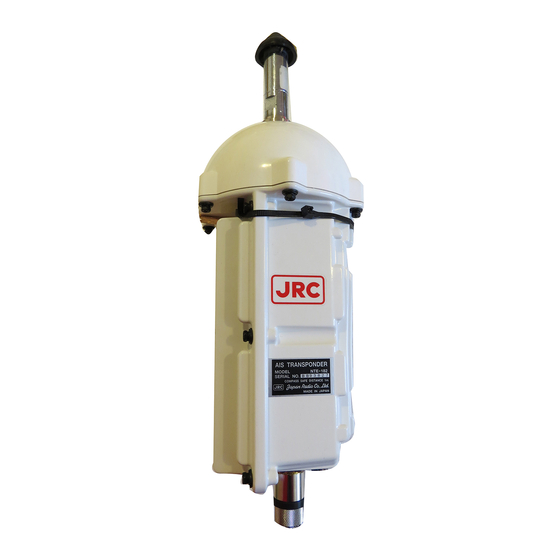
- Page 5 1 Outline and Installation Drawings 1-1 NTE-182 AIS Transponder Unit: mm Mass: approx. 2.6kg Color: N9 Outline Drawing of NTE-182 AIS Transponder...
- Page 6 NTE-182 AIS Transponder Rubbers (Attachment) Ground bolt Cautions (Dock supply) 1. *1: Seal this section with self-bonding tape and then wrap with Ground sheet vinyl tape. (Attachment) 2. *2: When the cable length is 500 mm Fixing belts or longer, fix it with metal belts along the pole.
- Page 7 Rubbers (Attachment) Ground bolt NTE-182 AIS Transponder (Dock supply) Cautions Ground sheet 1. *1: Seal this section with self-bonding (Attachment) tape and then wrap with vinyl tape. 2. *2: When the cable length is 500 mm Fixing belts or longer, fix it with tie-wraps along (Attachment) the pole.
- Page 8 Dia.-60.5 AIS Transponder (50A) Dia.-101.6 (90A) Steel board Hex head bolt for grounding (M8 x 20FE) (JIS G 3141) Don’t paint. Pole or Mast (JIS G 3141) Steel pipe Dia.60.5 – Dia.101.6 (50A – 90A) Dia.- 60.5 (50A) Φ101.6 Dia.-101.6 (90A) (90A) Reference Drawing...
- Page 9 Note 1. Materials Pipe: JIS standard 60.5mm dia. (t4.2), 101.6mm dia. (t4.2), or equivalent Other plates: SPHC equivalent Screw: M8 x 20 FE hexagon head screw 2. Coating: Fine particle coating P-N9 Coating range: Whole outside face excluding thread grooves (Coating may be spilt over inside the pipe.) 3.
- Page 10 Note 1. Materials Pipe: JIS standard 60.5mm dia. (t4.2), 101.6mm dia. (t4.2), or equivalent Other plates: SPHC equivalent Screw: M8 x 20 FE hexagon head screw 2. Coating: Fine particle coating P-N9 Coating range: Whole outside face excluding thread grooves (Coating may be spilt over inside the pipe.) 3.
- Page 11 Separate it from the transponder by 45 mm 50 x 6FB Ground bolt Handrail Handrail (25A SGP) Ground sheet Detail of section C M8 x 20L Ground bolt PL Dia.55 x t 6 19 x 4FB 50 x 12FB Pole or Mast Detail of section B Reference Drawing for NTE-182 Transponder Installation Support (Zinc Galvanizing)
- Page 12 Separate it from the transponder by 45 mm 50 x 6FB Ground bolt Handrail Handrail (25A SGP) Ground sheet Detail of section C M8 x 20L Ground bolt PL Dia.55 x t 6 Pole or Mast Flat surface There is not distortion by the welding. Detail of section B Detail of section A Reference Drawing for NTE-182 Transponder...
- Page 13 Fixing procedure Note: Prepare the following parts: 1 washer W8 Ground sheet Rubbers 10 x 10 x 10 1 spring washer SW8 AIS Transponder 1 hexagon nut N8 (1) Stick Rubbers on the AIS Transponder. (2) Attach with Protection sheet around the pole. (3) Adjust the length of the ground sheet to fit the pole or mast, bend it, and cut it off.
- Page 14 Connection Procedure of Coaxial Connector 1. Parts (N-P-10U) Armor Tightening Gasket Washer Clamp Ring Center contact Insulator Connector housing clamp bracket (rubber) 2. Procedure Working Shape Remarks step Cut the metal braid armor and insulation sheath as shown left. Ravel the braid conductor and cut the insulator as shown left.
- Page 15 Working Shape Remarks step 1. Insert the conductor while melting solder in the center contact. 2. Be sure that no space is left between the center contact and insulator. 3. Check the hole that solder flows between the Insulator conductor and center contact. Be sure that solder covers the conductor sufficiently and Center contact does not protrude outside the center contact.
- Page 16 1-1 NQD-4382 Junction Box (Option) Cable gland 10b Cable gland 30a Unit: mm Mass: approx. 1.4kg Outline Drawing of Color: 7.5BG7/2 NQD-4382 Junction Box...
- Page 17 To NTE-182 AIS Transponder Seal this section with a sealing material made from silicon. Vinyl-shielded wire 7 strands and 0.45mm diameter, or equivalent Gather and twist shielding braided wires and solder to the vinyl-shielded wire. Seal this section with a sealing material made from silicon.
- Page 18 1-2 NCM-779 AIS Controller Unit: mm Mass: approx. 1.0kg Color: N4 Outline Drawing of NCM-779 AIS Controller...
- Page 19 MAINTENANCE connector Connector for Maintenance PC is available inside the cover. Connect terminal to the Ship ground. Nameplate Pilot Plug Serial number of the equipment Pilot Plug for Personal Pilot Unit is is printed on the plate. available on the rear. POWER/DATA connector Attached cable connects between AIS controller and Connection Box.
- Page 20 dimensions of a hole in the wall COUNTERSINK for M3 . . Pilot Plug Unit : mm Console Mounting Kit (1) Mounting board 1pc (2) Screw (M4 x 8Bs) 4pcs (3) Self-tap-screw 6pcs Console Mounting Kit (Option) for NCM-779 AIS Controller...
Need help?
Do you have a question about the JHS-182 and is the answer not in the manual?
Questions and answers