Advertisement
Quick Links
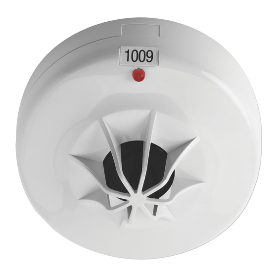
ZP700 Series Addressable Detector
Installation Sheet
1
3
EN: Installation Sheet
Description
ZP700 Series Addressable Detector models are shown below.
Table 1: Models
Number
Description
ZP720-3P
Addressable Thermal Sensor, Polar White
ZP730-2P
Addressable Optical Smoke Sensor, Polar White
ZP732-2P
Combination Smoke and Heat Detector, Polar White
Figures
Figure 1: Inserting the detector
Figure 2: Position of the locking tab
Figure 3: Removing a locked detector
Figure 4: Setting the address
© 2021 Carrier. All rights reserved.
2
4
Installation
Note:
For general guidelines on system planning, design,
installation, commissioning, use and maintenance, refer to the
EN 54-14 standard and local regulations.
To install a detector:
Insert the detector head into the mounting base and rotate it
clockwise until it clicks into place (Figure 1).
The detector may be locked into the mounting base if required.
To do this, remove the locking tab before installation shown in
Figure 2.
After installation, ensure that the detector communicates with
the control panel. Always test detectors after installation.
To remove a locked detector:
1.
Insert a small screwdriver into the locking tab slot
(Figure 3).
2.
Press and rotate the detector anticlockwise.
1 / 4
P/N 10-4211-501-ZP01-02 • ISS 04OCT21
Advertisement

Related Manuals for Ziton ZP700 Series


Summary of Contents for Ziton ZP700 Series
- Page 1 EN 54-14 standard and local regulations. Description ZP700 Series Addressable Detector models are shown below. To install a detector: Insert the detector head into the mounting base and rotate it Table 1: Models clockwise until it clicks into place (Figure 1).
- Page 2 Setting the address Dimensions (Ø x H) 106 × 52 mm ZP720-3P The detectors include a seven-segment DIP switch (SW1) for 106 × 52 mm ZP730-2P assigning device addresses. Each switch segment has a 106 × 58 mm ZP732-2P decimal value as shown in Figure 4. The address is the sum of Weight all the switch segments in the ON position.
- Page 3 Product warnings and disclaimers THESE PRODUCTS ARE INTENDED FOR SALE TO AND INSTALLATION BY QUALIFIED PROFESSIONALS. CARRIER FIRE & SECURITY B.V. CANNOT PROVIDE ANY ASSURANCE THAT ANY PERSON OR ENTITY BUYING ITS PRODUCTS, INCLUDING ANY “AUTHORIZED DEALER” OR “AUTHORIZED RESELLER”, IS PROPERLY TRAINED OR EXPERIENCED TO CORRECTLY INSTALL FIRE AND SECURITY RELATED PRODUCTS.
- Page 4 4 / 4 P/N 10-4211-501-ZP01-02 • ISS 04OCT21...