Table of Contents

Related Manuals for Groupe Atlantic NAVISTEM B1000

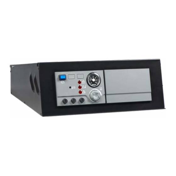
Summary of Contents for Groupe Atlantic NAVISTEM B1000
- Page 1 Document No. 0TA0Z0109-B / 01.02.2018 NAVISTEM B1000 CONTROL PANEL FOR STEEL SHELL BOILERS Instructions for installation, use and maintenance MANUFACTURER: SITE DE CAUROIR Route de Solesmes FR - 59400 CAUROIR...
- Page 2 NAVISTEM B1000 - Installation, use and maintenance Page 2 / Variable: Book Number of pages 0TA0Z0109-B...
-
Page 3: Warnings And Compliance
NAVISTEM B1000 - Installation, use and maintenance 1. WARNINGS AND COMPLIANCE Unpacking and reservations With the carrier present, carefully check the general appearance of the packaging and of the control panel. If in doubt, do not use the appliance. In the case of any dispute, state any appropriate reservations to the carrier in writing within 48 hours and send a copy of this letter to the After-Sales service. - Page 4 NAVISTEM B1000 - Installation, use and maintenance Electromagnetic compatibility (2004/108/CEE) • This appliance conforms with all requirements of the electromagnetic compatibility directive EN61000 - 6 - 1, EN61000 - 6 - 3. • This is a class A appliance. In a residential environment, this appliance may cause radio-electric interference.
-
Page 5: Table Of Contents
NAVISTEM B1000 - Installation, use and maintenance CONTENTS 1. WARNINGS AND COMPLIANCE ..................3 2. TECHNICAL SPECIFICATIONS ..................6 2.1. General ................................. 6 2.2. Dimensions ..............................6 2.3. Delivered unit ..............................6 2.4. Technical data ............................... 7 2.5. Thermostat module ............................8 2.6. -
Page 6: Technical Specifications
NAVISTEM B1000 - Installation, use and maintenance 2. TECHNICAL SPECIFICATIONS 2.1. General The NAVISTEM B1000 control panel commands the boiler's burner via a two-stage control thermostat. 2.2. Dimensions figure 1 - Dimensions (in mm) 2.3. Delivered unit • Sheet metal casing •... -
Page 7: Technical Data
The control thermostat must be set taking into account the temperature WARNING: constraints of the boiler on which the NAVISTEM B1000 control panel is used (temperature limit to avoid condensation in the heat exchanger). Edition: 02 / 2018... -
Page 8: Thermostat Module
NAVISTEM B1000 - Installation, use and maintenance 2.5. Thermostat module figure 2 - Thermostat module Legend F1: 6.3 AH 250 V AC Burner / Boiler fuse F2: 6.3 AH 250 V AC heating regulator fuse — Not used F3: 6.3 AH 250 V AC additional heating regulator fuse — Not used Safety thermostat (reset button) First stage and second stage control thermostat. -
Page 9: Basic Control Panel Equipment
NAVISTEM B1000 - Installation, use and maintenance 2.6. Basic control panel equipment Thermostat module Connector for alarm relay board Burner connection terminal Connection terminal to release the burner's operation Power supply and connection terminal of safety devices specific to the installation Connection terminal to release operation of the burner's second speed. -
Page 10: Installation
NAVISTEM B1000 - Installation, use and maintenance 3. INSTALLATION 3.1. Installation of the control panel The control panel must be fitted and installed in the intended position on WARNING: the boiler. 3.1.1. Opening the control panel Remove the screws on the cover. -
Page 11: Fitting The Sensors (Bulbs)
NAVISTEM B1000 - Installation, use and maintenance 3.1.3. Fitting to the side of the boiler • Pass the three capillaries (thermometer, control thermostat, safety thermostat) through the oblong hole 1 on support 2. • Fit the control panel 3 with the studs to support 2 fitted on the boiler's side jacket. - Page 12 NAVISTEM B1000 - Installation, use and maintenance 1 or 2 sensors 3 sensors figure 9 - Installation of sensors A: Foam seal Ø 8 mm B: Sensor • To get a correct temperature reading, insert the sensors with the Ø 8 mm foam seal.
- Page 13 NAVISTEM B1000 - Installation, use and maintenance 3.2.3. MELBURY HE3800 to HE10000 boilers Position of sensors F4: Safety thermostat F5: Control thermostat Thermometer figure 11 - MELBURY HE3800 to HE10000 boilers 3.2.4. MELBURY HE530 to HE3000 boilers Position of sensors...
-
Page 14: Electrical Connection
NAVISTEM B1000 - Installation, use and maintenance 3.3. Electrical connection The electrical diagram is attached to the control panel. It is stuck under the INFORMATION: cover. WARNING: Do not pull the electrical cables. Remove them from heat sources. Only carry out electrical connections, in particular connection to the main WARNING: supply, when all other fitting and installation work is completed. - Page 15 NAVISTEM B1000 - Installation, use and maintenance 3.3.1. Control panel cabling diagram Safety Control thermostat thermostat T6.3AH T6.3AH T6.3AH 250VAC 250VAC 250VAC 1 2 3 4 Burner power supply Command for 1st-stage of burner Command for 2nd-stage of burner 1 2 3 4 5 6...
- Page 16 NAVISTEM B1000 - Installation, use and maintenance 3.3.2. Burner cables • Pass the burner connection cables through the rubber membrane 1 and position them between the insulation and the boiler's casing. figure 16 - Burner cables and outlet sensor Do not remove or alter the boiler's insulation. Ensure there is no direct WARNING: contact between the cables and the heat exchanger.
- Page 17 NAVISTEM B1000 - Installation, use and maintenance 3.3.4. Connection of the control panel's electrical power supply and external safety in- terlock connections Control panel's electrical power supply: 230 V AC 50Hz Maximum intensity: 16 A Type of cable: 3 G 2.5 mm²...
- Page 18 NAVISTEM B1000 - Installation, use and maintenance 3.3.5. Burner connection Burner's electrical power supply: 230 V AC 50 Hz Maximum intensity: 6.3 A Type of cable: 3 G 1.5 mm² Burner's electrical commands: 230 V AC 50 Hz Maximum intensity: 6.3 A Type of cable: 3 G 1.5 mm²...
- Page 19 NAVISTEM B1000 - Installation, use and maintenance 3.3.7. Connection of the cable to enable operation of the burner's second stage Connection of the cable to ensure operation of the burner at second stage: 230 V (AC) 50Hz Maximum intensity 6.3 A Type of cable: 1.5 mm²...
-
Page 20: Additional Accessories
NAVISTEM B1000 - Installation, use and maintenance 4. ADDITIONAL ACCESSORIES Each additional accessory is delivered with its own instructions (fitting, electrical connections and use). 4.1. Accessories Alarm relay board without potential (A123) ..........Ref. 059808 • Relay of the following information in the form of contacts without potential:... -
Page 21: Using The Control Panel
NAVISTEM B1000 - Installation, use and maintenance 5. USING THE CONTROL PANEL 5.1. Start-up (Commissioning) 5.1.1. Setting the control thermostat • Turn the thumbwheel 1 to the desired water temperature (see the value on the thermometer); • Stopping pins are positioned behind the... -
Page 22: Breakdown Maintenance
NAVISTEM B1000 - Installation, use and maintenance 5.1.3. Switching the burner on • ON/OFF switch 1 for the burner's power supply. figure 27 - Burner's ON/OFF switch INFORMATION: The switch is lit up when the burner is on. 5.2. Breakdown maintenance... - Page 23 NAVISTEM B1000 - Installation, use and maintenance 5.2.2. External safety interlock circuit LED lit up If the external safety interlock circuit LED is lit up, refer to the external appliance which is connected to terminals 3, 4 and 5 of the control panel to identify the fault, find the cause and eliminate it.
-
Page 24: Spare Parts List
NAVISTEM B1000 - Installation, use and maintenance 6. SPARE PARTS LIST Reference Description 76320 ON / OFF switch for burner 76321 Thermometer - water temperature 76322 Control thermostat - 2 stage (without knurled wheel) 76323 Safety thermostat 76324 LED indicator... - Page 25 NAVISTEM B1000 - Installation, use and maintenance Edition: 02 / 2018 Page 25 / Variable : Livre Nombre de pages...
- Page 26 NAVISTEM B1000 - Installation, use and maintenance Page 26 / Variable : Livre Nombre de pages 0TA0Z0109-B...
- Page 27 NAVISTEM B1000 - Installation, use and maintenance Edition: 02 / 2018 Page 27 / Variable : Livre Nombre de pages...
- Page 28 ATLANTIC BELGIUM SA SATC ATLANTIC SOLUTIONS CHAUFFERIE Avenue du Château Jaco, 1 1 route de Fleurville 1410 WATERLOO 01190 PONT DE VAUX Tel. : 02/357 28 28 Tél. : 03 51 42 70 03 Fax : 02/351 49 72 Fax : 03 85 51 59 30 www.ygnis.be www.atlantic-guillot.fr YGNIS ITALIA SPA...
Need help?
Do you have a question about the NAVISTEM B1000 and is the answer not in the manual?
Questions and answers