Chapters
Table of Contents

Related Manuals for Groupe Atlantic NAVISTEM B2000

Summary of Contents for Groupe Atlantic NAVISTEM B2000
- Page 1 Document No. 0TA0Z0110-C / 01.02.2018 NAVISTEM B2000 CONTROL PANEL FOR CLASSIC BOILERS Instructions for installation, use and maintenance MANUFACTURER: SITE DE CAUROIR Route de Solesmes FR - 59400 CAUROIR...
- Page 2 NAVISTEM B2000 - Installation, use and maintenance Page 2 / 76 0TA0Z0110-C...
-
Page 3: Table Of Contents
NAVISTEM B2000 - Installation, use and maintenance CONTENTS 1. WARNINGS AND COMPLIANCE ..................4 2. TECHNICAL SPECIFICATIONS ..................6 2.1. General ................................. 6 2.2. Dimensions ..............................6 2.3. Delivered unit ..............................6 2.4. Technical data ............................... 7 2.5. Thermostat module ............................8 2.6. -
Page 4: Warnings And Compliance
NAVISTEM B2000 - Installation, use and maintenance 1. WARNINGS AND COMPLIANCE Unpacking and reservations With the carrier present, carefully check the general appearance of the packaging and of the control panel. If in doubt, do not use the appliance. In the case of any dispute, state any appropriate reservations to the carrier in writing within 48 hours and send a copy of this letter to the After-Sales service. - Page 5 NAVISTEM B2000 - Installation, use and maintenance Electromagnetic compatibility (2004/108/CEE) • This appliance conforms with all requirements of the electromagnetic compatibility directive EN61000 - 6 - 1, EN61000 - 6 - 3. • This is a class A appliance. In a residential environment, this appliance may cause radio-electric interference. In this case, the user may be asked to take appropriate measures.
-
Page 6: Technical Specifications
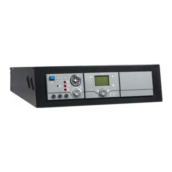
NAVISTEM B2000 - Installation, use and maintenance 2. TECHNICAL SPECIFICATIONS 2.1. General The NAVISTEM B2000 control commands the boiler's burner and heating circuits depending on the installation. All elements of the installation can thus be handled and commanded easily from one place. -
Page 7: Technical Data
NAVISTEM B2000 - Installation, use and maintenance 2.4. Technical data Name of manufacturer YGNIS INDUSTRIE Unique reference NAVISTEM B2000 Single-phase power supply 230 VAC 50Hz Rated current 16 A Casing protection index IP20 Reference operating temperature Degree of pollution Degree of pollution II... -
Page 8: Thermostat Module
NAVISTEM B2000 - Installation, use and maintenance 2.5. Thermostat module figure 2 - Thermostat module Legend 1: F1: 6.3 AH 250 V AC Burner / Boiler fuse 2: F2: 6.3 AH 250 VAC Heating regulator fuse (RVS63) 3: F3: 6.3 AH 250 V AC additional heating regulator fuse(sold as an accessory) 4: Safety thermostat (reset button) 5: First speed and second speed control thermostat (inactive on a NAVISTEM B2000 control panel). -
Page 9: Basic Control Panel Equipment
NAVISTEM B2000 - Installation, use and maintenance 2.6. Basic control panel equipment 1: Thermostat module 2: Connector for alarm relay board 3: Additional power supply connector RVS46 4: Burner connection terminal 5: Connection terminal to release the burner's operation 6: Power supply and connection terminal of safety devices specific to the installation 7: Accessory terminal for three-phase burner power supply (not included with control panel. -
Page 10: Regulation/Regulator
NAVISTEM B2000 - Installation, use and maintenance 2.7. Regulation/Regulator figure 4 - Regulation/Regulator 1: Display AVS37 (supplied with accessory RVS46) 2: Display AVS37 (basic NAVISTEM B2000 control panel equipment) 3: Additional regulator sold as accessory RVS46 (with display) 4: Regulator RVS63 (basic NAVISTEM B2000 control panel equipment) 5: Regulation electronic board (basic NAVISTEM B2000 control panel equipment) 2.7.1. Heating regulator RVS63 + display AVS37 The regulator allows the following: • Command of a one-speed, two-speed or modulating burner • Command of a direct heating circuit •... - Page 11 NAVISTEM B2000 - Installation, use and maintenance The RVS 63 regulator is protected with a 6.3 A fuse. The total load of WARNING: the consuming elements (pumps, mixing valves, isolation valves, etc.) connected to this regulator must not be more than 6.3 A.
-
Page 12: Installation
NAVISTEM B2000 - Installation, use and maintenance 3. INSTALLATION 3.1. Installation of the control panel The control panel must be fitted and installed in the position intended for this on WARNING: the boiler. 3.1.1. Opening the control panel Remove the screws on the cover. figure 5 - Opening the control panel Keep the screws from the control panel's cover. They are specific and DANGER: ensure grounding continuity. -
Page 13: Fitting Sensors (Bulbs Or Flow Sensors)
NAVISTEM B2000 - Installation, use and maintenance 3.1.3. Fitting to the side of the boiler • Pass the three capillaries (thermometer, control thermostat, safety thermostat) through the oblong hole 1on support2. • Fit the control panel 3 with the studs to support 2 fitted on the boiler's side jacket. • Fit the control panel to the support on the boiler's side jacket using the sheet metal screws included. - Page 14 NAVISTEM B2000 - Installation, use and maintenance 1 or 2 sensors 3 sensors figure 10 - Installation of sensors A: Foam seal Ø 8 mm B: Sensor • To get a correct temperature reading, insert the sensors with the Ø 8 mmfoam seal.
- Page 15 NAVISTEM B2000 - Installation, use and maintenance Position of sensors F4: Safety thermostat Control thermostat Boiler sensor (QAZ36) Thermometer B7: Return sensor (contact sensor, QAD36). Not supplied with the control panel figure 12 - LRP 3.2.3. LRR Position of sensors F4: Safety thermostat Control thermostat Boiler sensor (QAZ36) Thermometer...
-
Page 16: Electrical Connection
NAVISTEM B2000 - Installation, use and maintenance 3.2.5. LRK Position of sensors Safety thermostat Control thermostat Boiler sensor (QAZ36) Thermometer Return sensor (immersion sensor, QAZ36) to be ordered as an accessory. Not supplied with the control panel S11: RT Recuperator thermostat (not included with the control panel). figure 15 - LRK 3.3. Electrical connection The electrical diagram is attached to the control panel. It is stuck under the INFORMATION: cover. - Page 17 NAVISTEM B2000 - Installation, use and maintenance Area for signal cables (VLV: voltage less than 20V DC). Area for low voltage cables (LV: between 50V AC and 400V AC). figure 16 - Cabling DANGER: Comply with the cabling areas and separation of LV and VLV cables. Edition: 02 / 2018 Page 17 / 76...
- Page 18 NAVISTEM B2000 - Installation, use and maintenance 3.3.1. Control panel cabling diagram Safety Control thermostat thermostat T6.3AH T6.3AH T6.3AH 250VAC 250VAC 250VAC 1 2 3 4 Burner power supply Command for 1st-stage of burner Command for 2nd-stage of burner 1 2 3 4 5 6...
- Page 19 NAVISTEM B2000 - Installation, use and maintenance 3.3.2. Burner cables and flow sensor • Pass the burner connection and the boiler flow sensor cables through the rubber membrane and position them between the insulation and the boiler's jacket. figure 18 - Burner cables and flow sensor Do not remove or alter the boiler's insulation. Ensure there is no direct WARNING: contact between the cables and the heat exchanger.
- Page 20 NAVISTEM B2000 - Installation, use and maintenance 3.3.4. Connection of the control panel's electrical power supply and external safety con- nections Control panel's electrical power supply: 230 V AC 50 Hz Maximum intensity: 16 A Type of cable: 3 G 2.5 mm² External safety connections: 230 V AC 50 Hz Remove the shunt between 3 and 4 to...
- Page 21 NAVISTEM B2000 - Installation, use and maintenance 3.3.5. Burner connection Burner's electrical power supply: 230 V AC 50Hz Maximum intensity: 6.3A Type of cable: 3 G 1.5 mm² Burner's electrical commands: 230V AC 50Hz Maximum intensity: 6.3A Type of cable: 3 G 1.5 mm² figure 21 - Burner connection For connection details see "...
- Page 22 NAVISTEM B2000 - Installation, use and maintenance 3.3.7. Connection to heating regulator RVS63 INFORMATION: For more information, refer to the instructions for the RVS63 regulator. Connection of other sensors and signals: Maximum 20 V DC Maximum intensity: see instructions for RVS63 Type of cable: 0.5 mm² Connection of contact sensors QAD36 (2 sensors for the heating circuits, 1 cascade flow sensor, 1 return sensor).
- Page 23 NAVISTEM B2000 - Installation, use and maintenance For details for connecting to regulator RVS63, see " Selection diagram " INFORMATION: page <?>. 3.3.8. Closing the control panel When all connections have been made, close the control panel. WARNING: To close the control panel, use the screws you previously removed. Ensure each cable gland is tight so that no connection inside the control WARNING: panel can be attempted.
-
Page 24: Additional Accessories
NAVISTEM B2000 - Installation, use and maintenance 4. ADDITIONAL ACCESSORIES Each additional accessory is delivered with its own instructions (fitting, electrical connections and use). 4.1. Temperature sensors 4.1.1. Sensors included with the control panel • 1 immersion sensor (boiler sensor) QAZ36: (CTN 10 kΩ; 25°C) Ref. 059261 Fitting: inside the boiler's thimble (flow). QAZ36: L=6m Protection: IP43 Measuring range: 0..95°C... -
Page 25: Remote Control Qaa75
NAVISTEM B2000 - Installation, use and maintenance • Sensor with immersion cable (DHW sensor) QAZ36: (CTN 10 kΩ; 25°C) Ref. 059261 Fitting: inside the thimble on the DHW tank, minimum depth 51mm. QAZ36: L= 6 m Protection: IP42 Measuring range: 0..95°C • Sensor with immersion cable (burnt gas sensor): (PT 1000 Ω; 0°C) Ref. 059815 To measure the temperature of burnt gases. -
Page 26: Other Accessories
NAVISTEM B2000 - Installation, use and maintenance 4.3. Other accessories Alarm relay board without potential (A123) ......... Ref. 059808 • Relay of the following information in the form of contacts without potential: Burner speed 1 Burner speed 2 Burner problem signal Safety thermostat problem signal External errors signal (safety elements specific to the installation) Alarm relay board without potential (A123) + Burner remote resetting module .. -
Page 27: Using The Control Panel
NAVISTEM B2000 - Installation, use and maintenance 5. USING THE CONTROL PANEL 5.1. Start-up (Commissioning) 5.1.1. Setting the regulation thermostat to its maximum value • Put the thumbwheel in the maximum position to position the thermostat's axis; • Remove the thumbwheel; figure 25 - Thumbwheel in maximum position • Put the stopping pin in the maximum position. -
Page 28: Breakdown Maintenance
NAVISTEM B2000 - Installation, use and maintenance 5.1.3. Configuration of regulator RVS63 See paragraph 6 and the instructions for regulator RVS63 included in the INFORMATION: control panel to configure the heating regulator. 5.1.4. Switching the burner on • ON/OFF switch for the burner's power supply. figure 27 - Burner's ON/OFF switch INFORMATION: The switch is lit up when the burner is on. - Page 29 NAVISTEM B2000 - Installation, use and maintenance 5.2.2. Overheating LED lit up If the overheating LED is lit up, find the cause of overheating and repair if necessary. Once the problem has been solved, it is necessary to manually switch back on the safety thermostat. The safety thermostat can only be reset if the temperature has decreased WARNING: by 20°C in relation to the overheating temperature of 110°C.
- Page 30 NAVISTEM B2000 - Installation, use and maintenance 5.2.5. Replacing fuses • Fuse F1 protects the burner line • Fuse F2 protects the regulation of the NAVISTEM B2000 control panel. • Fuse F3 protects the additional regulation sold as an accessory.
-
Page 31: Hydraulic Diagrams And Configurations
NAVISTEM B2000 - Installation, use and maintenance 6. HYDRAULIC DIAGRAMS AND CONFIGURATIONS 6.1. Symbols used in the diagrams Symbol Function Symbol Function Isolation valve open Balancing valve 2-channel powered valve Motor-controlled 3-way valve Pump External sensor Temperature sensor 6.2. List of diagrams BURNER ............................. 2 1 speed ................................. -
Page 32: Burner
NAVISTEM B2000 - Installation, use and maintenance Burner - page 1 / 2 1 speed HYDRAULIC DIAGRAM CLASSIC BOILER WITH 1-SPEED BURNER figure 30 - Diagram for 1-speed burner ELECTRICAL CONNECTION figure 31 - Electrical connection Page 32 / 76... - Page 33 NAVISTEM B2000 - Installation, use and maintenance Burner - page 2 / 2 1 speed CONFIGURATION " " Make the burner's electrical connection. " " Make the following settings: Line No. Value • Configuration menu Set the type of generator Type of generator (5770)
-
Page 34: Speeds
NAVISTEM B2000 - Installation, use and maintenance Burner - page 1 / 2 2 speeds HYDRAULIC DIAGRAM CLASSIC BOILER WITH 2-SPEED BURNER figure 32 - Diagram for 2-speed burner ELECTRICAL CONNECTION figure 33 - Electrical connection Page 34 / 76... - Page 35 NAVISTEM B2000 - Installation, use and maintenance Burner - page 2 / 2 2 speeds CONFIGURATION " " Make the burner's electrical connection. " " Make the following settings: Line No. Value • Configuration menu Set the type of generator Type of generator (5770)
-
Page 36: Modulating 3-Position
NAVISTEM B2000 - Installation, use and maintenance Burner - page 1 / 2 modulating 3-position HYDRAULIC DIAGRAM CLASSIC BOILER WITH 3-POINT MODULATING BURNER figure 34 - Diagram for modulating 3-position burner ELECTRICAL CONNECTION figure 35 - Electrical connection Page 36 / 76... - Page 37 NAVISTEM B2000 - Installation, use and maintenance Burner - page 2 / 2 modulating 3-position CONFIGURATION " " Make the burner's electrical connection. " " Make the following settings: Line No. Value • Configuration menu Set the type of generator Type of generator (5770)
-
Page 38: Modulating 0
NAVISTEM B2000 - Installation, use and maintenance Burner - page 1 / 2 modulating 0...10 Volts HYDRAULIC DIAGRAM CLASSIC BOILER WITH 0-10V MODULATING BURNER figure 36 - Diagram for modulating 0...10-volt burner ELECTRICAL CONNECTION figure 37 - Electrical connection Page 38 / 76... - Page 39 NAVISTEM B2000 - Installation, use and maintenance Burner - page 2 / 2 modulating 0...10 Volts figure 38 - Regulator connection CONFIGURATION " " Make the burner's electrical connection. " " Make the following settings: Line No. Value • Configuration menu Set the type of generator...
-
Page 40: Single Boiler
NAVISTEM B2000 - Installation, use and maintenance LRPK / LRP NT+, management of flow page 1 / 3 Single boiler - protection with action on consumers HYDRAULIC DIAGRAM MANAGEMENT OF ALL ESSENTIAL SECONDARY NETWORKS OR LPB BUSES CLASSIC BOILER WITH 1 OR 2... - Page 41 NAVISTEM B2000 - Installation, use and maintenance Single boiler - page 2 / 3 LRPK / LRP NT+ figure 41 - Regulator connection CONFIGURATION " " Make the sensor's electrical connections. " " Start up the boiler. " " Set the date and time: Line No.
- Page 42 NAVISTEM B2000 - Installation, use and maintenance Single boiler - page 3 / 3 LRPK / LRP NT+ " " Set the boiler's settings: • Boiler menu Minimum flow temperature of boiler Minimum setpoint (2210) 50°C (for fuel oil) 60°C (for gas) Maximum flow temp. setpoint of boiler Maximum setpoint (2212) 85 °C Nominal power of boiler (Maximum...
- Page 43 NAVISTEM B2000 - Installation, use and maintenance LRP / LRK / LR / LRR, management of page 1 / 3 Single boiler - protection of returns with action on consuming elements HYDRAULIC DIAGRAM MANAGEMENT OF ALL ESSENTIAL SECONDARY NETWORKS OR LPB BUSES...
-
Page 44: Lrp / Lrk / Lr / Lrr, Management Of Protection Of Returns With Action On Consuming Elements
NAVISTEM B2000 - Installation, use and maintenance LRP / LRK / LR / LRR, management of page 2 / 3 Single boiler - protection of returns with action on consuming elements figure 44 - Regulator connection CONFIGURATION " " Make the sensor's electrical connections. - Page 45 NAVISTEM B2000 - Installation, use and maintenance LRP / LRK / LR / LRR, management of page 3 / 3 Single boiler - protection of returns with action on consuming elements " " Configure the boiler according to its type (see page 32, “Burner” and following) and remember to activate defect management. • Boiler menu...
-
Page 46: Lrp / Lrk / Lr / Lrr, Management Of Protection Of Returns Without Compulsory Command Of Consuming Elements
NAVISTEM B2000 - Installation, use and maintenance LRP / LRK / LR / LRR, management of page 1 / 3 Single boiler - protection of returns without compulsory command of consuming elements HYDRAULIC DIAGRAM CLASSIC BOILER WITH 1 OR 2... - Page 47 NAVISTEM B2000 - Installation, use and maintenance figure 46 - Electrical connection LRP / LRK / LR / LRR, management of page 2 / 3 Single boiler - protection of returns without compulsory command of consuming elements figure 47 - Regulator connection CONFIGURATION "...
- Page 48 NAVISTEM B2000 - Installation, use and maintenance LRP / LRK / LR / LRR, management of page 3 / 3 Single boiler - protection of returns without compulsory command of consuming elements " " Configure the boiler according to its type (see page 32, “Burner” and following) and remember to activate defect management. • Boiler menu...
-
Page 49: Homogeneous Cascade
NAVISTEM B2000 - Installation, use and maintenance LRPK / LRP NT+, management of flow page 1 / 4 Homogeneous cascade - protection with action on secondary networks HYDRAULIC DIAGRAM MANAGEMENT OF ALL ESSENTIAL SECONDARY NETWORKS OR LPB BUSES CLASSIC BOILER WITH 1 OR 2... - Page 50 NAVISTEM B2000 - Installation, use and maintenance LRPK / LRP NT+, management of flow page 2 / 4 Homogeneous cascade - protection with action on secondary networks figure 50 - Connection of regulator to the first boiler (master) figure 51 - Connection of regulator to the second boiler (slave)
- Page 51 NAVISTEM B2000 - Installation, use and maintenance LRPK / LRP NT+, management of flow page 3 / 4 Homogeneous cascade - protection with action on secondary networks CONFIGURATION ON EACH BOILER " " Make the sensor's electrical connections. " "...
- Page 52 NAVISTEM B2000 - Installation, use and maintenance LRPK / LRP NT+, management of flow page 4 / 4 Homogeneous cascade - protection with action on secondary networks ON THE MASTER BOILER " " Define the cascade flow and return sensor (option): • Configuration menu Sensor input BX3 (5930)
-
Page 53: Lr / Lrr / Lrp / Lrk, Management Of Protection Of Returns On Boiler Pump Action And Management Of Secondary Networks
NAVISTEM B2000 - Installation, use and maintenance LR / LRR / LRP / LRK, management of page 1 / 4 Homogeneous cascade - protection of returns on boiler pump action and management of secondary networks HYDRAULIC DIAGRAM MANAGEMENT OF ALL ESSENTIAL... - Page 54 NAVISTEM B2000 - Installation, use and maintenance LR / LRR / LRP / LRK, management of page 2 / 4 Homogeneous cascade - protection of returns on boiler pump action and management of secondary networks figure 54 - Connection of regulator to the first boiler (master)
- Page 55 NAVISTEM B2000 - Installation, use and maintenance LR / LRR / LRP / LRK, management of page 3 / 4 Homogeneous cascade - protection of returns on boiler pump action and management of secondary networks CONFIGURATION ON EACH BOILER "...
- Page 56 NAVISTEM B2000 - Installation, use and maintenance LR / LRR / LRP / LRK, management of page 4 / 4 Homogeneous cascade - protection of returns on boiler pump action and management of secondary networks ON THE MASTER BOILER "...
- Page 57 NAVISTEM B2000 - Installation, use and maintenance LR / LRR / LRP / LRK, management of page 1 / 4 protection of returns via 3-channel valve Homogeneous cascade - without obligation to act on the consuming elements HYDRAULIC DIAGRAM CLASSIC BOILER WITH 1 OR 2 SPEED...
-
Page 58: Lr / Lrr / Lrp / Lrk, Management Of Protection Of Returns Via 3-Channel Valve Without Obligation To Act On The Consuming Elements
NAVISTEM B2000 - Installation, use and maintenance LR / LRR / LRP / LRK, management of page 2 / 4 protection of returns via 3-channel valve Homogeneous cascade - without obligation to act on the consuming elements figure 58 - Connection of regulator to the first boiler (master) - Page 59 NAVISTEM B2000 - Installation, use and maintenance LR / LRR / LRP / LRK, management of page 3 / 4 protection of returns via 3-channel valve Homogeneous cascade - without obligation to act on the consuming elements CONFIGURATION ON EACH BOILER "...
- Page 60 NAVISTEM B2000 - Installation, use and maintenance LR / LRR / LRP / LRK, management of page 4 / 4 protection of returns via 3-channel valve Homogeneous cascade - without obligation to act on the consuming elements ON THE MASTER BOILER "...
-
Page 61: Mixed Cascade
NAVISTEM B2000 - Installation, use and maintenance LRP NT+ with LRP / LR, protection of returns page 1 / 6 Mixed cascade - via 3-channel valve HYDRAULIC DIAGRAM MANAGEMENT OF ALL ESSENTIAL SECONDARY NETWORKS OR LPB BUSES CLASSIC BOILER WITH 1 OR 2... -
Page 62: Lrp Nt+ With Lrp / Lr, Protection Of Returns Via 3-Channel Valve
NAVISTEM B2000 - Installation, use and maintenance LRP NT+ with LRP / LR, protection of returns page 2 / 6 Mixed cascade - via 3-channel valve figure 62 - Connection of regulator on the first boiler (LRP NT+) figure 63 - Connection of the second boiler (LRP / LR) - Page 63 NAVISTEM B2000 - Installation, use and maintenance LRP NT+ with LRP / LR, protection of returns page 3 / 6 Mixed cascade - via 3-channel valve figure 64 - Connection of regulator on the second boiler (LRP / LR) CONFIGURATION ON LRP NT+ BOILER (master boiler) "...
- Page 64 NAVISTEM B2000 - Installation, use and maintenance LRP NT+ with LRP / LR, protection of returns page 4 / 6 Mixed cascade - via 3-channel valve " " Check the connection of the sensors: • Inputs/outputs test menu Temperature sensor BX3 (7822) in °C...
- Page 65 NAVISTEM B2000 - Installation, use and maintenance LRP NT+ with LRP / LR, protection of returns page 5 / 6 Mixed cascade - via 3-channel valve ON LRP / LR BOILER (back-up boiler) " " Make the sensor's electrical connections.
- Page 66 NAVISTEM B2000 - Installation, use and maintenance LRP NT+ with LRP / LR, protection of returns page 6 / 6 Mixed cascade - via 3-channel valve " " Configure as slave of the cascade: • LPB network menu Appliance address (6600) Segment address (6601) Clock operation (6640) Slave without...
-
Page 67: Heat Request
NAVISTEM B2000 - Installation, use and maintenance Heat request - page 1 / 5 Management of secondary networks The heat requests sent to the boiler(s) may differ. They may originate from one or several of the following applicants: • Heating circuit controlled by the controller • DHW circuit controlled by the controller • Consumer request not controlled by the controller via a 0...10V signal •... -
Page 68: Management Of Secondary Networks
NAVISTEM B2000 - Installation, use and maintenance Heat request - page 2 / 5 Management of secondary networks figure 67 - Heat request diagram- DHW production ELECTRICAL CONNECTION figure 68 - Electrical connection and connection of direct circuit Page 68 / 76... - Page 69 NAVISTEM B2000 - Installation, use and maintenance Heat request - page 3 / 5 Management of secondary networks figure 69 - Regulator connection CONFIGURATION Regulation of secondary networks by another machine and sending of a temperature setpoint via a 0...10V signal "...
- Page 70 NAVISTEM B2000 - Installation, use and maintenance Heat request - page 4 / 5 Management of secondary networks Constant flow temperature from generators or low level setting " " Configure the H1 input: Line No. Value • Configuration menu Input function H1 (5950) Minimum...
- Page 71 NAVISTEM B2000 - Installation, use and maintenance Heat request - page 5 / 5 Management of secondary networks " " Configure an anti-Legionella function: Line No. Value Anti-Legionella function (1640) - - - Periodic Legionella function (1641) - - - Legionella function per day week (1642) - - - Anti-Legionella setpoint (1645)
-
Page 72: Spare Parts List
Fuse holders 71898 Fuses 76325 Regulator thermostat knurled wheel with adjustment stop 72367 AVS37 display with AVS92 cover 76148 AVS37 - RVS63 display ribbon 72357 RVS63 without connectors 76328 NAVISTEM B2000 regulation plate 72359 RVS46 72358 QAA75 ambience unit 71122 QAD36 surface contact temperature sensor 62864 QAZ36 wired sensor 62860 QAC34 exterior sensor Page 72 / 76... - Page 73 NAVISTEM B1000 - Installation, use and maintenance Edition: 02 / 2018 Page 73 / 76...
- Page 74 NAVISTEM B1000 - Installation, use and maintenance Page 74 / 76 0TA0Z0110-C...
- Page 75 NAVISTEM B1000 - Installation, use and maintenance Edition: 02 / 2018 Page 75 / 76...
- Page 76 ATLANTIC BELGIUM SA SATC ATLANTIC SOLUTIONS CHAUFFERIE Avenue du Château Jaco, 1 1 route de Fleurville 1410 WATERLOO 01190 PONT DE VAUX Tel. : 02/357 28 28 Tél. : 03 51 42 70 03 Fax : 02/351 49 72 Fax : 03 85 51 59 30 www.ygnis.be www.atlantic-guillot.fr YGNIS ITALIA SPA YGNIS AG Via Lombardia, 56 Wolhuserstrasse 31/33...
Need help?
Do you have a question about the NAVISTEM B2000 and is the answer not in the manual?
Questions and answers