
Related Manuals for Hobart Inventor Series


Summary of Contents for Hobart Inventor Series
- Page 1 OM-281997E 2021-08 Inventor ™ OM-281997D 2019-11 Series Auto-Darkening Welding Helmets Inventor Series Auto-Darkening Welding Helmets OWNER’S MANUAL...
-
Page 2: Table Of Contents
TABLE OF CONTENTS SECTION 1 – SAFETY PRECAUTIONS – READ BEFORE USING......1 Symbol Usage ............. 1 Arc Welding Hazards . -
Page 3: Section 1 - Safety Precautions - Read Before Using
SECTION 1 – SAFETY PRECAUTIONS – READ BEFORE USING Protect yourself and others from injury—read, follow, and save these important safety precautions and operating instructions. 1-1. Symbol Usage DANGER! – Indicates a hazardous situation which, if not avoided, will result in death or serious injury. - Page 4 � Before welding, adjust the auto-darkening lens sensitivity setting to meet the application. � Stop welding immediately if the auto-darkening lens does not darken when the arc is struck. NOISE can damage hearing. Noise from some processes or equipment can damage hearing. �...
-
Page 5: California Proposition 65 Warnings
� Do not weld in locations near degreasing, cleaning, or spraying operations. The heat and rays of the arc can react with vapors to form highly toxic and irritating gases. � Do not weld on coated metals, such as galvanized, lead, or cadmium plated steel, unless the coating is removed from the weld area, the area is well ventilated, and while wearing an air- supplied respirator. -
Page 6: Principal Safety Standards
1-5. Principal Safety Standards Safety in Welding, Cutting, and Allied Processes, American Welding Society standard ANSI Standard Z49.1. Website: http://www.aws.org. Safe Practice For Occupational And Educational Eye And Face Protection, ANSI Standard Z87.1, from American National Standards Institute. Website: www.ansi.org. Safety in Welding, Cutting, and Allied Processes, CSA Standard W117.2 from Canadian Stand- ards Association. -
Page 7: Section 2 - Consignes De Sécurité - Lire Avant Utilisation
SECTION 2 – CONSIGNES DE SÉCURITÉ - LIRE AVANT UTILISATION Pour écarter les risques de blessure pour vous-même et pour autrui — lire, appliquer et ranger en lieu sûr ces consignes relatives aux précautions de sécurité et au mode opératoire. 2-1. - Page 8 � Avoir recours à des écrans protecteurs ou à des rideaux pour protéger les autres contre les rayonnements les éblouissements et les étincelles ; prévenir toute personne sur les lieux de ne pas regarder l’arc. � Porter un équipement de protection pour le corps fait d’un matériau résistant et ignifuge (cuir, coton robuste, laine).
-
Page 9: Proposition Californienne 65 Avertissements
LES FUMÉES ET LES GAZ peuvent être dangereux. Le soudage produit des vapeurs et des gaz. Respirer ces vapeurs et ces gaz peut être dangereux pour votre santé. � Écarter la tête des fumées. Ne pas inhaler ces fumées. � À l’intérieur, ventiler la zone et/ou utiliser une ventilation forcée au niveau de l’arc pour l’éva- cuation des fumées et des gaz de soudage. -
Page 10: Principales Normes De Sécurité
Classe de N° de classe Taille d'électrode Courant d'arc protection Procédé de protection in. (mm) en ampères suggérée minimum (Comfort)* Léger Moins de 500 Coupage arc-air (CAC-A) Lourd 500–1000 Moins de 20 20–40 40–60 Coupage à l'arc 60–80 plasma 80–300 300–400 400–800 Moins de 20... -
Page 11: Section 3 - Specifications
SECTION 3 – SPECIFICATIONS Viewing Field 3.94 x 2.36 in. (100 x 60 mm) Reaction Time 0.00004 sec (1/25,000 sec) Available Shades Darkened State: No. 9–13/Light State: No. 3 Provides Continuous UV And IR Protection (DIN 15) Grind Mode Sensitivity Control Lo-Hi Adjustment For Varying Ambient Light And Welding Arc Delay Control Min-Max Adjustment Slows Lens Dark-To-Light State Between... -
Page 12: Section 4 - Operation
SECTION 4 – OPERATION 4-1. Helmet Controls SECTION 10 OPERATING INSTRUCTIONS 10-1. Helmet Controls � Remove protective films from lens before welding. 1 Low Battery Indicator (See Section 4-2) 2 Variable Shade Control (See Section 4-4) 3 Sensitivity Control (See Section 4-5) 4 Lens Delay Control (See Section 4-3) -
Page 13: Low Battery Indicator
4-2. Low Battery Indicator 10-2. Low Battery Indicator 1 Low Battery Indicator The low battery indicator lights when 2-3 days of battery life remain. If battery power is low, install new CR2450 lithium batteries (see Section 7-1). � The auto-darkening lens consumes less than 1 microamp battery... -
Page 14: Variable Shade Control (No. 9-13)
10-4. Variable Shade Control (No. 9–13) 4-4. Variable Shade Control (No. 9–13) � Place Weld/Grind mode switch in Weld position (Section 4-6). 1 Variable Shade Control (No. 9–13) Use the control to adjust the lens shade in the darkened state. Use the table in Section 1-4 to select proper shade control setting based on your welding process. -
Page 15: Sensitivity Control
10-5. Sensitivity Control 4-5. Sensitivity Control � Place Weld/Grind mode switch in Weld position (Section 4-6). 1 Sensitivity Control Use control to make the lens more responsive to different light levels in various welding processes. Use a Mid-Range or 50-70% sensitivity set- ting for most applications. -
Page 16: Weld/Grind Mode Switch
10-6. Weld/Grind Mode Switch 4-6. Weld/Grind Mode Switch 1 Weld/Grind Mode Switch 2 Grind Mode Indicator Place switch in Grind mode for grinding applications. To resume welding, place switch in Weld mode. The Grind Mode indicator will blink when helmet is in Grind mode. �... -
Page 17: Power Modes
10-7. Power Modes 4-7. Power Modes The auto-darkening lens has three power modes: sleep (off), standby, and on. The lens goes to sleep automati- cally when ambient light is low (less than 3 lux). The lens consumes less than 1 micro- amp of battery power when in the sleep mode. -
Page 18: Section 5 - Adjusting Headgear
SECTION 11 ADJUSTING HEADGEAR SECTION 5 – ADJUSTING HEADGEAR 5-1. Adjusting Headgear Slots on the right side of the headband pro- � There are four headgear adjustments: vide adjustment for the forward tilt of the hel- headgear top, tightness, angle adjust- met. -
Page 19: Section 6 - Replacing Lens Covers
SECTION 6 – REPLACING LENS COVERS 6-1. Replacing Outside Lens Cover SECTION 12 REPLACING THE LENS COVERS 12-1. Replacing Outside Lens Cover Never use the auto- darkening lens with- out the inside and outside lens covers properly installed. Welding spatter will damage auto- darkening lens and... -
Page 20: Replacing Inside Lens Cover
12-2. Replacing Inside Lens Cover 6-2. Replacing Inside Lens Cover Never use the auto- darkening lens with- out the inside and outside lens covers properly installed. Welding spatter will damage auto- darkening lens and void the warranty. 1 Lens Assembly 2 Inside Lens Cover Remove the lens cover holder (see Section 6-1). -
Page 21: Section 7 - Replacing The Battery
SECTION 13 REPLACING THE BATTERY SECTION 7 – REPLACING THE BATTERY 7-1. Replacing The Battery The helmet is powered by so- lar cells and two CR2450 lith- ium batteries. 1 Low Battery Indicator The low battery indicator lights when 2-3 days of battery life remain. -
Page 22: Section 8 - Installing Optional Magnifying Lens
SECTION 8 – INSTALLING OPTIONAL MAGNIFYING LENS 8-1. Installing Optional Magnifying Lens 1 Optional Magnifying Lens Slide magnifying lens into the helmet retaining brackets as shown. Align the magnifying lens with the auto-darkening lens assembly. � To prevent lens fogging, install flat side of magni- fying lens toward auto- darkening lens. -
Page 23: Section 9 - Maintenance And Troubleshooting
SECTION 9 – MAINTENANCE AND TROUBLESHOOTING 9-1. Maintenance And Storage � Do not use solvents or abrasive cleaning detergents to clean the helmet. Do not im- merse the lens assembly in water. � Keep helmet dry; do not expose helmet to rain or snow. Keep helmet away from fire and other sources of heat. -
Page 24: Troubleshooting
9-2. Troubleshooting Trouble Remedy Not switching – auto- Stop welding immediately. If power is on, review the sensitivity rec- lens stays light and ommendations and adjust sensitivity. Make sure helmet is not in does not darken when Grind mode. Clean lens cover and sensors of any obstructions. welding. -
Page 25: Section 10 - Parts List
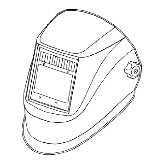
SECTION 15 PARTS LIST SECTION 10 – PARTS LIST Figure 10-1. Inventor Series Auto-Darkening Welding Helmet Figure 10-2. Inventor Series Auto-Darkening Welding Helmet OM-281997 Page 11 OM-281997 Page 23... - Page 26 10-1. Inventor Series Auto-Darkening Welding Helmet Item Part No. Description Qua- ntity 770847 Headgear 216714 Label, Warning, Helmet EN/SP/FR ♦770274 Diopter Lens 150X ♦770276 Diopter Lens 200X ♦770277 Diopter Lens 250X 770846 Auto-Darkening Lens 770284 Battery, CR2450 770883 Frame, Lens Replacement...
-
Page 27: Section 11 - Limited Warranty
Hobart Welding Products, Appleton, WI, warrants to its original retail purchaser that the new Hobart equipment sold after the effective date of this limited warranty is free of defects in material and workmanship at the time it is purchased at the retailer. THIS WARRANTY IS EX- PRESSLY IN LIEU OF ALL OTHER WARRANTIES, EXPRESS OR IMPLIED, INCLUDING THE WARRANTIES OF MERCHANTABILITY AND FITNESS. - Page 28 www.HobartWelders.com ORIGINAL INSTRUCTIONS – PRINTED IN USA © Miller Electric Mfg. LLC 2021-08...
Need help?
Do you have a question about the Inventor Series and is the answer not in the manual?
Questions and answers
Where can I find the rubber gasket #770612 for my Hobart hood-pro series decomposition #770765 This frame needs the rubber gasket