Table of Contents
Advertisement
Quick Links
Advertisement
Table of Contents

Related Manuals for Accorroni VMC PUNTUALE 65

Summary of Contents for Accorroni VMC PUNTUALE 65
- Page 1 RecuperatorI di calore VMC PUNTUALE, murali residenziali VMC PUNTUALE 65...
- Page 3 IMPORTANTE IMPORTANT PRIMA DI COMPIERE QUALUNQUE OPERAZIONE BEFORE PERFORMING ANY OPERATION OF THE MACHINE CAREFULLY READ, RIGUARDANTE LA MACCHINA LEGGERE ATTENTAMENTE, COMPRENDERE E SEGUIRE UNDERSTAND AND FOLLOW TUTTE LE ISTRUZIONI DEL PRESENTE MANUALE ALL INSTRUCTIONS LISTED IN THIS MANUAL INDICE INDEX SIMBOLOGIA UTILIZZATA SYMBOLS USED...
- Page 4 SYMBOLS USED SIMBOLOGIA UTILIZZATA La macchina è stata progettata e costruita in accordo alle The machine has been designed and constructed according norme vigenti ed è quindi dotata di sistemi di prevenzione e to the current norms and consequently with mechanical and protezione per i rischi di natura meccanica ed elettrica che electrical safety devices designed to protect the operator or user from possible physical damage.
-
Page 5: Note Importanti
IMPORTANT NOTES NOTE IMPORTANTI The units are designed and built exclusively for: Le unità sono progettate e costruite esclusivamente per: - internal installation. - installazioni interne. - per il trattamento aria degli ambienti civili, incompatibili - for air traitment in the civil environments, incompatible con gas tossici, esplosivi, infiammabili e corrosivi (incluse wit h toxic,... - Page 6 1 - CARATTERISTICHE TECNICHE 1 - TECHNICAL SPECIFICATIONS 1.1 TARGHETTATURA IDENTIFICATIVA 1.1 IDENTIFICATION LABELLING OF THE UNIT DELL’UNITA’ %-**-5(,& Fig. 1...
-
Page 7: Presentation Of The Manual
1 - CARATTERISTICHE TECNICHE 1 - TECHNICAL SPECIFICATIONS Nell’immagine seguente (Fig. 2) è riportata la posizione della In the picture below (Fig. 2) is showed the identify labels position. targhetta dati tecnici/identificativi. La mancanza della etichetta dalla macchina The lack of the labels from the recovery unit causes the non-compliance of the product: in comporta la non conformità... - Page 8 1 - TECHNICAL SPECIFICATIONS 1 - CARATTERISTICHE TECNICHE 1.4 PRINCIPIO DI FUNZIONAMENTO (Fig. 3-4) 1.4 OPERATING PRINCIPLE (Fig. 3-4) Il ventilatore VMC PUNTUALE è costitu ito da u n condotto The ventilator VMC PUNTUALE consists of the telescopic air aria telescopico con lunghezza regolabile in funzione dello duct with adjustable length regulated by position of the inner air duct inside the ou ter air du ct, the ventilation u nit and the spessore della parete con l’esterno, dall'unità...
- Page 9 1 - TECHNICAL SPECIFICATIONS 1 - CARATTERISTICHE TECNICHE 1.5 FLUSSI ARIA (Fig. 4) 1.5 AIR FLOWS (Fig. 4) VENTILATION MODE VENTILAZIONE Il ventilatore VMC PUNTUALE funziona in modalità di The ventilator VMC PUNTUALE runs in the air extract or air supply mode with a set speed.
- Page 10 1 - TECHNICAL SPECIFICATIONS 1 - CARATTERISTICHE TECNICHE 1.6 CARATTERISTICHE TECNICHE 1.6 TECHNICAL SPECIFICATIONS Il ventilatore è progettato per il montaggio attraverso la The ventilator is designed for through-the-wall mounting. • • parete. Il design telescopico ne consente l'installazione The telescopic ventilator design enables its installation in the walls from 230 mm to 420mm thickness for the ventilator nelle p a reti d a 230 mm a...
- Page 11 1 - CARATTERISTICHE TECNICHE 1 - TECHNICAL SPECIFICATIONS 1.7 DATI TECNICI UNITA' E DIMENSIONI 1.7 UNIT TECHNICAL DATA AND DIMENSIONS MODELLO / MODEL Portata aria/ mc/h 20/42/64 Air flow rate Alimentazione elettrica / V/Ph/Hz 230/1/50-60 Power supply Corrente assorbita massima / 0,08 Maximum load amperage Potenza elettrica assorbita massima /...
- Page 12 2 - TRASPORTO 2 - TRANSPORT 2.1 IMBALLAGGIO 2.1 PACKAGING The recovery unit and the accessories provided for Il recuperatore e gli accessori previsti per il montaggio sono • • tutti contenuti all’interno dell’imballo in cartone, che dovrà assembly are all contained within the cardboard packaging, rimanere integro fino al momento del montaggio.
-
Page 13: Norme Di Sicurezza
3 - INSTALLAZIONE E MESSA IN SERVIZIO 3 - INSTALLATION AND START UP 3.2 NORME DI SICUREZZA 3.2 SAFETY STANDARDS The Manufacturer declines all responsibility for the failure to La ditta costruttrice declina qualsiasi responsabilità per la mancata osservanza delle norme di sicurezza e di prevenzione comply with the Safety and Accident-prevention Standards di seguito descritte. -
Page 14: Installazione Dell'unità
3 - INSTALLATION AND START UP 3 - INSTALLAZIONE E MESSA IN SERVIZIO 3.4 SCELTA DEL LUOGO D'INSTALLAZIONE 3.4 CHOICE OF THE INSTALLATION SITE Accertarsi che nel posto scelto per l’installazione sia Make sure that the connection to the 230V / 50hz single- •... -
Page 15: Installazione E Messa In Servizio
3 - INSTALLATION AND START UP 3 - INSTALLAZIONE E MESSA IN SERVIZIO 2) Assemblare il condotto interno e il condotto esterno con 2) Assemble inner duct and outer duct together to adapt to the staffa, cuffia e anello siliconico per adattarli allo spessore della thickness of wall (Fig. - Page 16 3 - INSTALLATION AND START UP 3 - INSTALLAZIONE E MESSA IN SERVIZIO 4) Installare il condotto ventilatore attraverso il foro della parete 4) Install the ventilator through the wall hole from indoor, and dall'interno e tirare indietro il condotto tramite la staffa di pull back the duct by the adjust bracket (Fig.
- Page 17 3 - INSTALLATION AND START UP 3 - INSTALLAZIONE E MESSA IN SERVIZIO Posizionare il blocco ventilatore sulla parete interna della 7) Put the fan on the surface wall as the location (Fig. 19), which parete (Fig. 19), avendo preventivamente inserito il dado nella the bracket and the nut are installed on the fan in advance , that staffa superiore del blocco ventola interno.
-
Page 18: Avvertenze Generali
3 - INSTALLATION AND START UP 3 - INSTALLAZIONE E MESSA IN SERVIZIO 9) Installare il gruppo ventilatore sulla parete interna con gli 9) Install the fan on the surface wall. The fan is fixed with nut appositi dadi (Fig. 21). (Fig. -
Page 19: Descrizione Del Telecomando
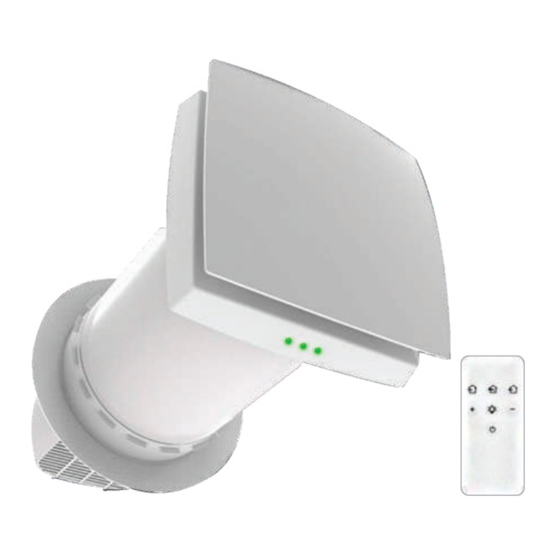
5 - REGOLAZIONE ELETTRONICA 5 - ELECTRONIC CONTROL 5.1 DESCRIZIONE DEL TELECOMANDO 5.1 DESCRIPTION OF REMOTE CONTROL L’unità è dotata di un telecomando con pulsantiera (Fig. 22), The unit is equipped with a remote control with push-button con le seguenti funzioni: panel (Fig. -
Page 20: Component Maintenance
6 - MANUTENZIONE ORDINARIA 6 - ROUTINE MAINTENANCE 6.1 INFORMAZIONI PRELIMINARI 6.1 PRELIMINARY INFORMATION Lack of maintenance, from the simplest one, can degrade La mancata manutenzione, a partire da quella elementare, • • può far degradare le prestazioni aerauliche e termiche air and heat performances, with consequent worsening of dell’apparato, con conseguente peggioramento del comfort room comfort. -
Page 21: Troubleshooting
6 - ROUTINE MAINTENANCE 6 - MANUTENZIONE ORDINARIA 6.2.3 PULIZIA DEI FILTRI 6.2.3 CLEANING FILTERS Pulire il filtro ogni volta che si sporca, ma almeno 3-4 volte Clean the filter as often as it gets dirty, but at least 3-4 times •... - Page 22 8 - DISPOSAL 8 - SMALTIMENTO Il simbolo (Fig. 27) indica che questo prodotto non deve essere The symbol indicates (Fig. 27) that this product must not be smaltito c ome rifiuto urbano misto e che per esso va praticata disposed of as mixed urban waste and that it must be collected una raccolta differenziata, in base alle leggi e normative locali.
- Page 24 A2B Accorroni E.G. s.r.l. Via d’Ancona, 37 - 60027 Osimo (An) - Tel. 071.723991 web site: www.accorroni.it - e-mail: a2b@accorroni.it...
Need help?
Do you have a question about the VMC PUNTUALE 65 and is the answer not in the manual?
Questions and answers