
Related Manuals for SPS PRO X 200

Summary of Contents for SPS PRO X 200
- Page 1 INSTRUCTION MANUAL T h e C o l u m n G a g e Sterling ProMeasure Systems...
-
Page 2: Table Of Contents
Instruction Manual Contents i. Contact information 1. Introduction 1.1 General information ......................: 1.2 Measuring and display features ..................: 1.3 Front and rear view ......................: 1.4 Dimensions ........................: 1.5 Hole pattern for interconnection ..................: 1.6 Technical data .........................: 2. Getting started 2.1 Delivered items .........................: 2.2 Fitting the base ........................: 2.3 Fitting the Bus modules ....................:... -
Page 3: Contact Information
Instruction Manual Contact Information... -
Page 4: Introduction
Instruction Manual Introduction 1.1 General information The PROX200 electronic column gage is an extremely ver- satile instrument, allowing the connection of 1 to 8 induc- tive or incremental probes, pneumatic gage heads, sensors with analog current or voltage outputs and gages with digi- tal interfaces. -
Page 5: Front And Rear View
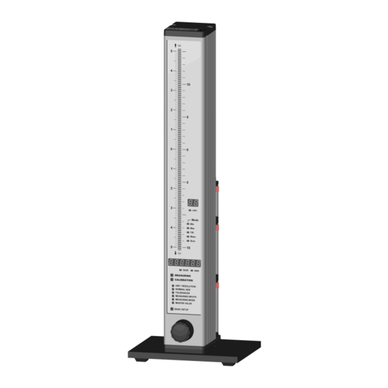
Instruction Manual � Column display ranges � 5.0000 mm � 0.50000 � The 3-color column display (red, green, yellow) � 1.5000 mm � 0.15000 � features an automatic color selection according � 0.5000 mm � 0.05000 � to the tolerance limits adjusted. �... -
Page 6: Dimensions
Instruction Manual Dimensions Picture : Column display with base 1.5 Hole pattern for interconnection... -
Page 7: Technical Data
Instruction Manual 1.6 Technical data Mechanical characteristics Case Aluminum anodized, plastic top and bottom parts Base Aluminum powder-coated Front panel Acryl glass Control element Rotary encoder with pushbutton function (16 detents per rotation) Dimensions W x H x D / Weight 56 x 418.5 x 86 mm / 1340g ( incl. -
Page 8: Getting Started
Instruction Manual Getting started 2.1 Delivered items Column gage, base with 4 screws (M3x8) for fixing, instruction manual, programming card, and a 2.0 mm Allen key. Further accessories, such as Bus measuring controllers, power supply modules, measuring modules, foot switches or adapters according to delivery note. Please check the shipment for completeness and keep the packaging 2.2 Fitting the base 4 DIN 7984 M3 x 8... -
Page 9: Connecting The Bus Modules
Instruction Manual A PROX200 column gage that comprises Bus modules is configured in a fixed order. If one single PROX200 is to be configured, the power supply module (No. 1) always has to be fitted first, followed by the measuring controller module (No. 2) and then subsequently (starting with No. 3) the measuring and inter- face modules in any chosen order. -
Page 10: Fitting Of Bus Terminator
Instruction Manual Important : Should an Bus module already be equipped with bolts (e.g. PS2 when using an CAS adapter ca- , please replace the bolts with 2 cross-recessed screws SH-UNC / 4-40*9.5 ble) in order to enable connecting of modules. (included in shipment) 2.3.3 Fitting of bus terminator Prior to inserting the modules into the column profile, the bus terminator connector is attached to... -
Page 11: Fitting Bus Modules Into The Prox200 Column Gauge
Instruction Manual 2.3.4 Fitting Bus modules into the PROX200 column gage Once the Bus modules have been connected, they are slid into the PROX200 column section as a package from the top and are then screwed to the column base using both cross-recessed screws. Do not overtighten screws! If modules have already been fitted into the PROX200 column and additional modules are to be in- stalled, then all previously fitted modules must be removed first. -
Page 12: Measuring Input Addresses
Instruction Manual 2.4 Measuring input addresses Bus terminator connector The measuring inputs are referred to as P1 to P8 for subsequent programming. The bottom measuring input is always P1. It is possible to connect more than 8 measuring inputs, the PROX200 column gage, however, can only address and read in the first 8 inputs. -
Page 13: Connecting Several Column Gauges
Instruction Manual 2.5 Connecting several column gages CAS type adapter cables are utilized to connect several column gages. The adapter cables fulfil two tasks : 1.) Transferring the supply voltage from the first column gage to the next. One power supply module can supply power to a maximum of 3 column gages, depending on the connected probes, sensors and measuring instruments. -
Page 14: Power Supply Connection
Instruction Manual Example 2 : connecting 5 column gages The five column gages are linked together via four CAS adapter cables. The cables are always fitted in the bottom positions, as shown in the illustration. The measurement inputs are passed on from the thinner adapter section to- wards the thicker adapter section. -
Page 15: Connecting A Foot Or Hand Switch
Instruction Manual 2.7 Connecting a foot or hand switch The foot or hand switches are connected to the Sub-D ports Ft1 and Ft2 of the MC1 measuring controller. Foot and hand switches can be cascaded in order to synchronize several column gages (e.g. -
Page 16: Connecting A Pc, Multiplexer Or Statistic Printer
Instruction Manual 2.9 Connecting a PC, multiplexer or statistic printer A PC , a multiplexer or a statistic printer can be connected at the rear panel of the (COM 1… 8, USB) column gage via the RS232 Sub-D port of the MC1 measuring controller. PC-RS232 cable PC-USB cable RSD-ADP (Mitutoyo Digimatic) -
Page 17: Connection Of Probes, Air Plug Gauges, Sensors And Measuring Instruments
Instruction Manual 2.11 Connection of probes, air plug gages, sensors and measuring instruments The modular design in conjunction with the BUS measuring and interface modules makes it possible to connect virtually any probe, pneumatic gage head, sensor or measuring instrument to the column gage. - Page 18 Instruction Manual Example 3 : Connection of pneumatic gage heads The column gage allows the connection of up to 8 pneumatic measuring converters AE1. An 8-by-6 mm hose connector (8 mm -> outer diameter; 6 mm -> inner diameter) is used to establish the com- pressed air supply.
-
Page 19: Power On / Self-Test
Instruction Manual 2.12 Power on / Self-test Every time the column gage is switched on, a self-test will automatically be performed in order to check all system components. If an error is detected during the self-test, the numeric display will indicate an er- ror message. -
Page 20: Programming The Column Gauge
Instruction Manual Programming the column gage The rotary encoder on the front panel is used to make all settings and carry out any programming. During programming the user is guided through the individual menus, step by step, and prompted by the LED and numeric displays. -
Page 21: Quick Programming Guide For Programmers In A Hurry
Instruction Manual 3.3 Quick programming guide for programmers in a hurry Menu selection and programming 1. Turn the encoder clockwise (CW) to switch to the programming mode. Turn the encoder counterclockwise (CCW) to exit the programming mode. 2. The respective display element that can be changed flashes in the programming mode. 3. -
Page 22: Description Of The Calibration Mode
Instruction Manual Description of the calibration mode Turn the encoder clockwise (CW) to select the CALIBRATION menu and then push the encoder button to access the menu. Three functions are available in the calibration mode : 1. Zero adjustment (one master, CAL.1 flashes) or calSPSation (two masters, CAL.1 / CAL.2 flashes) 2. -
Page 23: Probe Setup
Instruction Manual 3.4.2 Probe setup Inductive probes achieve their greatest degree of accuracy within a comparatively small measuring range only. It is therefore extremely important to carefully set up the probes at the electric zero point. On selection of the AdJuSt menu, the two-digit numeric display shows the measuring input P1 and the six-digit numeric display indicates the “raw value”... -
Page 24: Description Of The Programming Menu
Instruction Manual 3.5 Description of the programming mode Turn the encoder clockwise (CW) to switch from the Measuring Mode to the Programming Mode. - The six-digit numeric display indicates ‘ProGr.’. Programming menus : You can select the first menu by pushing the encoder button. The (UNIT / RESOLUTION - LED flashes) menu allows selecting both the Unit of Measurement and the measurement Resolution. - Page 25 Instruction Manual Turn the encoder to select the desired number of the flashing point and then confirm by pushing the encoder button. The nominal value determines the value at which the zero point is indicated on the column (no deviation) display.
- Page 26 Instruction Manual The MEASURING INPUTS menu enables assigning the measuring inputs (P1 to P8) to the currently se- lected gage (C1…C8). The 8 inputs can be linked in any order (e.g.: P1+P2, P1-P2, P1+P2 - P3+P4, etc.). Every measuring input can be multiplied by a “device coefficient” (multiplier) ranging from 0.001 to 59.999.
- Page 27 Instruction Manual P1 - P2 _ P3 - P4 d) Angle measurement : Angle = Angle = 0.5 P1 – 0.5 P2 – 0.5 P3 + 0.5 - 0.5 - 0.5 Note : If all measuring inputs are switched off, the numeric display of the column gage will indicate ‘Err.
- Page 28 Instruction Manual Turn the encoder to select the desired number of the flashing point and then confirm by pushing the en- coder button. - The first master value is programmed - The numeric display now flashes and indicates “2nd on” or “2nd off”. Turn the encoder to select whether a zero adjustment or a gage calibration with two masters (requires one master only, “2nd off”)
-
Page 29: Basic Setup
Instruction Manual 3.6 Basic setup The Basic Setup menu comprises all basic device settings which are usually only programmed during the initial operation. The basic factory setting is identified by an in the individual menus. Push the encoder button to select the menu. Turn the encoder to browse through the individ- GAGES ual gages from C1 to C8. - Page 30 Instruction Manual In the Basic Setup menus L2 to L5 controlling of the PROX200 via the encoder button and the foot or hand switch connections Ft1, Ft2 as well as the IMB foot switch Ft3 is set. The encoder button and each one of the 3 foot or hand switch connections can be assigned any function from the list.
- Page 31 Instruction Manual The activation of the trAnS mode freeze-frames the numeric and column display of the trAnS PROX200 column gage. Every time a programmed input (Encoder button, Ft1, Ft2, Ft3) is actuated, the currently measured value will be displayed. The activation of the hold mode effects that the display is freeze-framed while the hold programmed input is actuated (Encoder button, Ft1, Ft2, Ft3).
- Page 32 Instruction Manual The grading mode can be activated or deactivated independently for each gage (C1 to C8) in GrAdE this menu. The number of grading groups (classes) can be set from 1 to 30 and determines in how many, equal fields the tolerance range is split.
-
Page 33: Restoring Factory Settings
Instruction Manual PASS.Cd. For the protection of calibration and / or programming data, password protection can be activated in this menu. The numeric display will prompt the assignment of a six-digit password for password protection of calibration or programming data. Note : If the calibration menu or the programming menu is selected later on, the column gage prompts the entry of the six-digit password. -
Page 34: Error Messages / Corrective Actions
Instruction Manual 3.8 Error messages / Corrective actions The numeric display indicates Operating and Programming Errors caused by the user as well as System Errors of the column gage. 3.8.1 Operating and programming errors : error message (Err), error number (xx) Err. -
Page 35: System Errors
Instruction Manual 3.8.2 System errors System errors are displayed in the event of hardware problems. These error messages assist our service department in analysing the problem. Switch off the device and then switch it on again. Error Error description Corrective action The PROX200 does not receive any meas- 1. -
Page 36: Working With The Column Gauge
Instruction Manual Working with the column gage 4.1 Initial operation � Start by fitting the base and connecting the accessories (probes, foot switches, etc.). Follow the instructions given in chapter 2 of this manual. � Then programme the column gage for your application. Follow the instructions given in chapter 3 of this manual. -
Page 37: Restrictor Adjustment On Modules
Instruction Manual 4.4 Restrictor adjustment on AE1 moduls Restrictor adjustment with 2 masters : Use the encoder to select the “CALIBRATION” menu. The calibration menu is password protected, if the numeric display indicates “PASS.Cd.”. (See BASIC SETUP “LA – PASS.Cd.”) Select the Adjust function by turning the encoder (“AdJuSt”... -
Page 38: Automatic Zero Adjustment Of Gauges
Instruction Manual 4.5 Automatic zero adjustment of gages Place the master in the measuring device Use the encoder to select and start the “CALIBRATION” menu. The calibration menu is password protected, if the numeric display indicates “PASS.Cd.” (See BASIC SETUP “LA – PASS.Cd.”) The numeric display alternately indicates “CAL. - Page 39 Instruction Manual Note : This operating mode is preferred mainly for applications with several bore gages. End of Document...
Need help?
Do you have a question about the PRO X 200 and is the answer not in the manual?
Questions and answers