Advertisement
L1987
Rev. B
IMPORTANT RECEIVING INSTRUCTIONS
Visually inspect all components for shipping damage. If any shipping damage is found, notify
carrier at once. Shipping damage is NOT covered by warranty. The carrier is responsible for all
repair or replacement cost resulting from damage in shipment.
DESCRIPTION
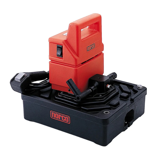
The 910052A Electric Pump is highly portable, yet it's powerful enough to handle many maintenance,
fabrication, construction, and lifting applications. The standard remote pendant makes any job
easier and safer. See specifi cations below.
Operating Pressure
Electrical Power Source
Motor Rating
Flow Rating
Operating Temperature
Reservoir Capacity
Shipping Weight
06/13
Instruction Sheet
910052A Electric Pump
SPECIFICATIONS
0 - 10,000 psi
15 Amp, 120 VAC grounded, single-phase, 50/60 Hz
1/2 HP Universal, 9 Amps @ 10,000 psi and 12,000 RPM
operates at 85-125 VAC, 85 - 89 dBA
200 cubic inches/minute @ 0-200 psi
20 cubic inches/minute @ 200 - 10,000 psi
150ºF
1 gallon
39 lbs
Advertisement
Table of Contents

Related Manuals for Norco 910052A


Summary of Contents for Norco 910052A
- Page 1 DESCRIPTION The 910052A Electric Pump is highly portable, yet it’s powerful enough to handle many maintenance, fabrication, construction, and lifting applications. The standard remote pendant makes any job easier and safer. See specifi cations below.
-
Page 2: Safety Information
SAFETY INFORMATION WARNING Do not use electric pumps in an explosive atmosphere. Adhere to all local and national electrical codes. WARNING Do not use hoses, fi ttings or couplers with pressure ratings below 10,000 psi. Install pressure gauges in the system to monitor operating pressure. WARNING Electric pumps have relief valves installed under the pump cover. -
Page 3: Operation
OPERATION Pump Switch (remote on/off/ momentary on) Pendant Switch Vent Plug Adjustable Relief Valve 1. Keep power cords reasonably short to avoid power losses between the power outlet and the pump. The pump will function at low voltage, but the speed and oil fl ow will be lower than normal. -
Page 4: Maintenance
RELIEF VALVE ADJUSTMENT 1. The main pump relief valve is internal and non-adjustable, factory set for 10,000 psi maximum operating pressure. An additional external relief valve is located under a hex cap on the right side of the pump. The external relief valve is adjustable from 10,000 psi down to 2000 psi. 2. -
Page 5: Troubleshooting
The Troubleshooting Chart (see below) is intended as a guide to help you diagnose and correct various possible pump problems. Only qualifi ed hydraulic technicians should troubleshoot and service the pump. For repair service, contact the Norco Authorized Service Center in your area. TROUBLESHOOTING CHART Pump will not start. -
Page 6: Test Standards
EC Directives 2006/42/EC, 97/23/EC, 2004/108/EC, 2006/95/EC and 97/23/EC. WARRANTY REPAIR SERVICE This Norco product is covered by a Limited Lifetime Warranty. If your Norco product requires service or repair, contact the Norco Customer Service Department for the location of the For details see the back cover of Norco's product catalog.
Need help?
Do you have a question about the 910052A and is the answer not in the manual?
Questions and answers