
Related Manuals for Bil-Jax 5031A


Summary of Contents for Bil-Jax 5031A
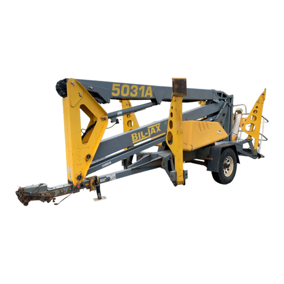
- Page 1 Parts and Service Manual AERIAL WORK PLATFORMS 5031A Hydraulic Boom Lift B33-01-0092...
- Page 2 BOOM PERSONNEL LIFT This equipment is designed and manufactured in compliance with the duties, responsibilities, and standards set forth for manufacturers in the ANSI 92.2 standard in effect at the time of manufacture. This equipment will meet or exceed applicable OSHA codes and ANSI A92.2 standards when used in accordance with sections 7, 8, 9 &...
-
Page 3: Table Of Contents
Table of Contents PREFACE ....................iv Safety........................1-1 Introduction.....................1-1 Before Operation..................1-3 During Operation ..................1-4 Maintenance Safety.................1-5 Damaged Equipment Policy..............1-7 Introduction.....................2-1 General Description ................2-1 Specifications ..................2-4 Warranty ....................2-5 Operation ......................3-1 Operator Controls..................3-1 Normal Operating Procedure ..............3-7 Emergency Lowering................3-9 Manual Boom Operations ..............3-10 Manual Boom Rotation .................3-11 Battery Recharge (DC Model Only) .............3-12 Boom Lift Transport ................3-14 Operator Service .....................4-1... - Page 4 List of Illustrations Figure 2-1. Bil-Jax 5031A Hydraulic Boom Lift............2-1 Figure 2-2. Platform and Ground Station Controls ........... 2-2 Figure 2-3. Safe Operating Zone................2-3 Figure 3-1. Pump Compartment Access ..............3-1 Figure 3-2. Ground Station Controls................. 3-3 Figure 3-3.
- Page 5 List of Tables Table 1-1. Minimum Safe Approach Distances............1-4 Table 2-1. Specifications ...................2-4 Table 3-1. Charger Fault Codes................3-13 Table 4-1. Daily/Weekly Service Checks..............4-1 Table 4-2. Monthly Service Checks ................4-2 Table 4-3. Troubleshooting Chart ................4-19 Table 4-4. Level Sensor LEDs ................4-25 Table 5-1.
-
Page 6: Preface
PREFACE The purpose of this manual is to provide a thorough understanding of the Bil-Jax 5031A Hydraulic Boom Lift operation and maintenance procedures. Read the safety, operating and maintenance instructions in this manual and become familiar with the location and use of all controls. -
Page 7: Safety
The information contained herein is not to be considered as legal advice and is intended for informational purposes only. This information is offered to alert Bil-Jax customers procedures that may be of concern to them. This information is not intended to be all inclusive and is to be followed in the use of Bil-Jax equipment only. - Page 8 BIL-JAX 5031A SAFETY NOTES This manual contains DANGERS, WARNINGS, CAUTIONS, and NOTES that must be followed to prevent the possibility of improper service, personnel injury or death, and damage to equipment. DANGER Dangers warn of equipment operation near electrical power lines that could lead to personal injury or death.
-
Page 9: Before Operation
1 — SAFETY BEFORE OPERATION Ensure the following general safety precautions are followed before operating the Bil-Jax 5031A Hydraulic Boom Lift. • ALWAYS survey the usage area for potential hazards such as untamped earth fills, unlevel surfaces, overhead obstructions, and electrically charged conductors or wires. -
Page 10: During Operation
BIL-JAX 5031A DURING OPERATION Ensure the following general safety precautions are followed during the operation of the Bil-Jax 5031A Hydraulic Boom Lift. DANGER This machine is not insulated for use near electrical power lines and DOES NOT provide protection from contact with or close proximity to any electrically charged conductor. -
Page 11: Maintenance Safety
NEVER leave the keys in the boom lift while unattended or not in use. MAINTENANCE SAFETY Ensure the following safety precautions are observed whenever maintenance is performed on the 5031A Hydraulic Boom Lift. General Maintenance • ALWAYS perform maintenance procedures according to manufacturer's requirements. - Page 12 NEVER touch or allow metal tools to contact static discharge sensitive electronic components. ALWAYS use static discharge prevention mats and grounding devices when handling electronic components. • NEVER tamper with cylinder counter balance valves. Contact the Bil-Jax Service Department at 800-537-0540 if the cylinder counter balance valves need adjusting. •...
-
Page 13: Damaged Equipment Policy
DAMAGED EQUIPMENT POLICY Safety Statement At Bil-Jax, we are dedicated to the safety of all users of our products. Therefore, all Bil-Jax lifts are designed, manufactured and tested to comply with current applicable Federal OSHA and ANSI codes and regulations. - Page 14 If you believe that your vehicle has a defect which could cause a crash or could cause injury or death, you should immediately inform the National Highway Traffic Safety Administration (NHTSA) in addition to notifying Bil-Jax, Inc. If NHTSA receives similar complaints, it may open an investigation, and if it finds that a safety defect exists in a group of vehicles, it may order a recall and remedy campaign.
-
Page 15: Introduction
Introduction GENERAL DESCRIPTION The Bil-Jax 5031A Hydraulic Boom Lift (Figure 2-1) is designed to position personnel with their to ols and equipment at overhead work locations. The work platform load capacity is 475 lbs. During all boom operations, the unit is supported by four extended outriggers. -
Page 16: Figure 2-2. Platform And Ground Station Controls
BIL-JAX 5031A The battery powered boom lift uses a 24 Volt, one horsepower, DC motor to drive the hydraulic pump. The DC motor is powered by four 6 Volt DC, 275 Amp-hour, deep charge batteries connected in series. A 40 Amp, automatic, on-board battery charger is provided for recharging the batteries at the end of each work period. -
Page 17: Figure 2-3. Safe Operating Zone
The Bil-Jax 5031A Hydraulic Boom Lift cylinders will not rust or corrode during storage since the cylinder rod is fully immersed in oil. It is important that the cylinder... -
Page 18: Specifications
BIL-JAX 5031A SPECIFICATIONS Boom Lift Work Platform Model Number: 5031A Serial Number ________________ Manufactured by: Bil-Jax, Inc. BIL-JAX AERIAL WORK PLATFORMS 125 Taylor Parkway Archbold, Ohio 43502 800-537-0540 Table 2-1. Specifications Feature Data Rated Platform Load 475 lbs (215 kg) total... -
Page 19: Warranty
2 — INTRODUCTION WARRANTY Bil-Jax warrants its boom lifts for one year from the date of delivery against all defects of material and workmanship, provided the unit is operated and maintained in compliance with Bil-Jax’s operating and maintenance instructions; structural components are warranted for three years. - Page 20 BIL-JAX 5031A...
-
Page 21: Operation
Operation OPERATOR CONTROLS The Bil-Jax 5031A Hydraulic Boom Lift is equipped with multiple operator controls. Outrigger controls are located only at ground level. Boom lift, extension, and rotation controls are located at ground level and in the work platform. Operator controls include a manual hydrauli c pump and pump handle. - Page 22 BIL-JAX 5031A Ground Station Controls The ground station controls (Figure 3-2) operate the outriggers and booms. Key Switch Turning the key to the left selects operation from the platform control station. Turning the key to the right selects operation from the ground control station. The center (Off) position disables electrical and hydraulic operations.
-
Page 23: Figure 3-2. Ground Station Controls
3 — OPERATION Figure 3-2. Ground Station Controls Outrigger Indicators Four green OUTRIGGER indicators light up when the boom lift outriggers are extended and the boom weight is carried by the outriggers. All four indicators must be lit and the trailer must be level to enable operation of the lift booms. -
Page 24: Figure 3-3. Pump Compartment
BIL-JAX 5031A Hydraulic Hand Pump The ground station controls include a hydraulic hand pump located inside the pump compartment (Figure 3-3). If lift boom operating power is lost, the hand pump is available to manually raise, lower, or rotate the lift boom. Holding the related operator lever in position and operating the hand pump raises, lowers, or rotates the boom. -
Page 25: Figure 3-5. Platform Control Station
3 — OPERATION Platform Control Station The platform control station (Figure 3-5) operates the hydraulic boom lift, boom extension, boom rotation, and the platform rotation and leveling motions. The platform control station includes the following electrical and hydraulic controls. Figure 3-5. Platform Control Station Emergency Stop Pushbutton When pressed, the EMERGENCY STOP pushbutton disconnects electrical power from the upper and lower control stations. - Page 26 BIL-JAX 5031A Boom Operator Levers Seven boom operator levers position proportional hydraulic valves to extend and retract three boom lift cylinders, the boom extension cylinder, the boom rotation drive motor, and the platform rotation and leveling cylinders. Pulling a boom operator lever up extends the cylinder to raise the boom.
-
Page 27: Normal Operating Procedure
3 — OPERATION NORMAL OPERATING PROCEDURE Perform the following procedures to operate the Bil-Jax 5031A Hydraulic Boom Lift. Read and follow all safety precautions contained in Section 1 and all responsibilities outlined in the ANSI A92.2 reprint contained in Section 7 of this manual. - Page 28 BIL-JAX 5031A WARNING Always verify that the green outrigger LEDs light up when the outrigger feet become loaded. If an outrigger LED fails to light up or lights up before the outrigger foot becomes loaded, the limit switch or switch setting is faulty. Using the boom lift with a faulty limit switch or switch setting can cause severe injury, death, or damage to the equipment.
-
Page 29: Emergency Lowering
3 — OPERATION EMERGENCY LOWERING The Bil-Jax 5031A Boom Lift is equipped with two emergency descent (lowering) switches and two emergency lowering valves. These devices can be used to lower the platform in case of a power failure, a load shift, or other emergency situation. -
Page 30: Manual Boom Operations
BIL-JAX 5031A Figure 3-8. Emergency Lowering Valve MANUAL BOOM OPERATIONS A hydraulic hand pump is located in the pump compartment (Figure 3-9). In case of a power failure you can use the hand pump and one boom operator lever to manually lift, lower, or rotate the boom. -
Page 31: Manual Boom Rotation
3 — OPERATION MANUAL BOOM ROTATION The hydraulic boom lift is equipped with a slew motor bypass valve. The valve can be manually opened to allow manual boom rotation in case of a power failure or other emergency situation. NOTE: The manual hydraulic pump and boom rotation valve lever can be used to manually rotate the boom as described in paragraph 3-4. -
Page 32: Battery Recharge (Dc Model Only)
BIL-JAX 5031A BATTERY RECHARGE (DC MODEL ONLY) The DC model boom lift batteries should be recharged after each 8-hour work shift or more often if needed. When the boom lift is not in use, the batteries should be recharged at least once per week. -
Page 33: Table 3-1. Charger Fault Codes
3 — OPERATION b. If a battery fault is detected, a fault code (F1, F2, F3, F4, F5, or F9) appears on the CHARGE CURRENT display and the red CHECK BATTERY indicator LED lights. The fault codes and data are shown in Table 3-1. When the batteries reach the 80% charge condition the yellow 80% CHARGED indicator LED lights and the green CHARGING indicator LED begins to flash. -
Page 34: Boom Lift Transport
BIL-JAX 5031A BOOM LIFT TRANSPORT The boom lift trailer is a single axle trailer fitted with a two-inch ball hitch, hydraulic surge brakes, mechanical parking brake, breakaway safety cable, safety chains, brake lights, and side marker lights. Proper boom lift transport requires the correct hookup and inspection of these trailer components before towing. - Page 35 3 — OPERATION CAUTION Always cross and attach the safety chains before towing. Failure to attach safety chains properly will allow tongue to drop in case of ball hitch failure, resulting in serious damage to the trailer and equipment. Attach the trailer safety chains to the tow vehicle. Make sure the chains cross under the trailer tongue.
- Page 36 BIL-JAX 5031A 3-16...
-
Page 37: Operator Service
Operator Service SCHEDULED SERVICE CH ECKS Daily/Weekly Service Checks Perform the following daily/weekly service checks as listed in Table 4 Table 4-1. Daily /Weekly Service Chec Daily Service Check before use Weekly Check to see that all decals are present. Check that controls and indicators at ground and platform control stations operate properly. -
Page 38: Table 4-2. Monthly Service Checks
BIL-JAX 5031A Monthly Service Checks Perform the following monthly service checks as listed in Table 4-2. Table 4-2. Monthly Service Checks Every Every Every Service Check month 6 months 12 months Check/add hydraulic oil per paragraph 4-4. Clean battery terminals and battery charger operation. -
Page 39: Wheel Nut Torque Requirements
4 — OPERATOR SERVICE WHEEL NUT TORQUE REQUIREMENTS It is very important to apply and maintain the correct wheel bolt torque on the boom lift trailer. The wheel bolts must be evenly tightened to the following specified torque increments whenever a trailer wheel is removed and installed. Use the following tightening procedure: ·... -
Page 40: Lubrication
BIL-JAX 5031A LUBRICATION Lubrication makes operation of the Bil-Jax 5031A Boom Lift more efficient and extends the equipment life. Use the following procedures to lubricate the boom lift components. Lubricate trailer jack post and all grease fittings labeled LUBRICATE WEEKLY with NLGI Grade 2 multi-purpose grease. -
Page 41: Hydraulic System
Only the adjustments covered in this manual are permitted. If you believe that any other hydraulic component needs adjustment, notify Bil-Jax for additional instruction. Hydraulic motions are quiet, quick, and can be dangerous to persons on or near the lift vehicle. Failure to heed this warning can result in serious injury or death. - Page 42 BIL-JAX 5031A Do not mix hydraulic oils. The reservoir is originally filled with Energol HLP-HD46, a high-grade, non-foaming hydraulic oil designed for temperatures as low as -20°F (- 33°C). For temperatures reaching -40°F (-40°C), use Dextron Automatic Transmission Fluid Type A.
-
Page 43: Figure 4-5. Main Relief Valve And Pressure Test Port (Gas Engine Model)
4 — OPERATOR SERVICE Hydraulic Pressure Checks and Adjustments Hydraulic pressures are set at the factory and should not be adjusted unless a hydraulic component has been replaced in the regulated circuit. On the gas engine model a pressure test port (Figure 4-5) is located at the ground station boom control valves. -
Page 44: Figure 4-6. Outriggers Relief Valve
BIL-JAX 5031A Adjust System Pressure Connect a hydraulic pressure gage to the pressure test port. Remove the cap from the outriggers relief valve (Figure 4-6). Turn the adjust screw to the right exactly two turns. This adjustment will force the main relief valve to regulate the test pressure. -
Page 45: Figure 4-7. Boom Control Relief Valve, Platform Station
4 — OPERATOR SERVICE Check/Adjust Outriggers Relief Pressure Pull up one outrigger control lever and read the pressure at the gage. If the gage reading is 2600 psig [180 bar (18 000 kPa)] nominal, no adjustment is required. If the outriggers relief pressure is too high or too low, remove the relief valve cap (Figure 4-6) and adjust the pressure. - Page 46 BIL-JAX 5031A Check and adjust the hydraulic relief pressure for the platform or ground station boom controls as follows: Connect a hydraulic pressure gage to the pressure test port. Start the gasoline engine or DC motor. Run the engine or motor for at least five minutes to warm the hydraulic oil to the normal operating temperature.
-
Page 47: Figure 4-8. Hydraulic Cylinder Removal
4 — OPERATOR SERVICE Boom Lift Cylinder Removal and Installation WARNING Make sure the boom and boom cylinder are securely supported before removing the boom cylinder. Failure to do so may cause the boom or boom cylinder to fall. This may cause severe injury or damage to the boom lift. If removing the lower boom lift cylinder, raise the lower boom to just above horizontal and stand a 36 inch (90 cm) long length of 4x4 hardwood shoring on the trailer tongue directly below the lower boom rest plate. - Page 48 Do not tamper with the cylinder counterbalance or manual lowering valves located on the boom lift cylinders. If the valves need adjustment, contact the Bil-Jax Service Department at 800-537-0540. Outrigger Cylinder Removal and Installation Lower the outrigger until the foot pad meets the floor and supports only the outrigger beam.
- Page 49 4 — OPERATOR SERVICE Drive out the pivot pin with a hammer and a brass or hardwood drift. Lift and remove the cylinder using an overhead hoist and lifting straps. After repairing the hydraulic cylinder, reinstall the cylinder in the reverse order of removal.
-
Page 50: Figure 4-9. Jib Boom Components
BIL-JAX 5031A Figure 4-9. Jib Boom Components Power up the hydraulic system and check for leakage. Tighten the hydraulic fittings as needed. Bleed entrapped air from the hydraulic cylinder according to instructions in paragraph 4-4. 4-14... -
Page 51: Figure 4-10. Platform Rotation Cylinder
4 — OPERATOR SERVICE Platform Rotation Cylinder Removal and Installation Fully lower the outriggers and raise the upper boom. Position the platform for easy access to the hydraulic cylinder (Figure 4-10) mounted on the bottom of the work platform. Figure 4-10. Platform Rotation Cylinder Place absorbent drip cloths below the cylinder ports. -
Page 52: Slew Ring Bearing
Repeat the measurement in step 5. Record the measurement. If the difference between the measurements in step 5 and step 9 is greater than 0.25 inch (6,35 mm) the slew ring bearing should be replaced. Notify Bil-Jax for bearing replacement instructions or assistance. -
Page 53: Limit Switch Checks And Adjustments
4 — OPERATOR SERVICE LIMIT SWITCH CHECKS AND ADJUSTMENTS Adjusting Boom Down Limit Switch When the upper and lower booms are retracted, the boom down limit switch is actuated. The boom down limit switch must be actuated to lower or raise the outriggers. The boom down limit switch should trip when the lower boom is within 2 inches (50 mm) of seating on the trailer tongue. -
Page 54: Figure 4-13. Outrigger Position Switch
BIL-JAX 5031A Adjusting Outrigger Position Switches The outrigger position switches are set up to detect when the boom lift load is transferred from the trailer wheels to the outriggers. When the load is transferred to each outrigger, the related position switch is engaged and the related LED lights up on the control panel. -
Page 55: Troubleshooting
4 — OPERATOR SERVICE TROUBLESHOOTING Table 4-3. Troubleshooting Chart Problem Cause Correction 1. Engine or motor will not Emergency stop engaged (pushed in). Rotate emergency stop buttons start. clockwise to disengage. b. Battery charge is low. b. Check charge level. Recharge battery if needed. - Page 56 BIL-JAX 5031A Table 4-3. Troubleshooting Chart, Continued 3. Pump motor runs, but upper Platform/ground key switch in wrong Turn key switch to enable platform or and lower boom lift position. ground controls. functions do not work. b. Boom lift out of level.
-
Page 57: Figure 4-14. Simplified Electrical Diagram, Dc Model
4 — OPERATOR SERVICE Troubleshooting Aids Electrical diagrams are provided in Figure 4-14 and Figure 4-15. Hydraulic diagrams are provided in Figure 4-16. Level sensor LED indications are shown in Table 4-4. FUSE 7.5A BATTERY PUMP MAIN MOTOR MOTOR 24 VDC DISCONNECT CONTACTOR –... -
Page 58: Figure 3-8. Emergency Lowering Valve
BIL-JAX 5031A UPPER CONTROL PANEL DEADMAN UPPER LOWER ESTOP EMERGENCY LOWERING POWER ON 27 28 26 25 PLATFORM 27 28 26 25 BASE LOWER CONTROL EMERGENCY LOWERING VALVE (LOWER BOOM LIFT RAM) UPPER LOWER 27 28 26 25 TILT ALARM... -
Page 59: Figure 4-4. Hydraulic Reservoir
4 — OPERATOR SERVICE GROUND CONTROL VALVE BANK 3200 PSI JIB BOOM TO LOWER CYLINDER BOOM LIFT CYLINDER TO UPPER BOOM LIFT TELESCOPIC TO PLATFORM CONTROL CYLINDER CYLINDER CONTROL VALVE BANK MANIFOLD BASE OUTRIGGER DIVERTER DIVERTER VALVE CT2 VALVE CT1 CT4A SOL1 SOL2... - Page 60 BIL-JAX 5031A PLATFORM CONTROL VALVE BANK FROM CONTROL MANIFOLD 3300 PSI TO BOOM ROTATION PLATFORM MOTOR ROTATION CYLINDER BOOM CYLINDER LOWER UPPER BOOM LIFT BOOM LIFT CYLINDER CYLINDER EMERGENCY EMERGENCY LOWERING LOWERING VALVE VALVE SOL3 SOL4 TELESCOPIC BOOM CYLINDER PLATFORM...
-
Page 61: Figure 4-17. Level Sensor
4 — OPERATOR SERVICE YELLOW LED GREEN LED RED LED OUT OF LEVEL INPUT POWER OUTPUT SIGNAL (MOMENTARY) (ON WHEN LEVEL) Figure 4-17. Level Sensor Table 4-4. Level Sensor LEDs Color Description Yellow Boom lift out of level. Signals alarm after 2 second delay. Green Boom lift power is on. -
Page 62: Material Safety Data Sheets
BIL-JAX 5031A MATERIAL SAFETY DATA SHEETS MATERIAL SAFETY DATA SHEET FOR LEAD ACID BATTERIES, WET, FILLED WITH ACID SECTION I: GENERAL INFORMATION Manufacturer’s Name: Crown Battery Mfg. Company EMERGENCY NO: 800 487-2879 Street Address: 1445 Majestic Drive 800 OIL-TANK City, State, Zip... - Page 63 4 — OPERATOR SERVICE MATERIAL SAFETY DATA SHEET FOR LEAD ACID BATTERIES, WET, FILLED WITH ACID (Continued) ******************************************************************************************** SECTION V -- HEALTH HAZARD DATA ******************************************************************************************** Primary Routes of Entry: Inhalation: Skin: Ingestion: Health Hazards: Acute EYES, SKIN, RESPIRATORY SYSTEM & DIGESTIVE SYSTEM Chronic: EYES, SKIN, RESPIRATORY SYSTEM &...
- Page 64 BIL-JAX 5031A MATERIAL SAFETY DATA SHEET FOR AW–46 HYDRAULIC OIL 1-SITE SPECIFIC INFORMATION: AW-46 HYDRAULIC OIL 2-GENERAL INFORMATION TRADE NAME: AW-46 HYDRAULIC OIL EMERGENCY TELEPHONE NUMBERS: (517) 849-2144 CHEMICAL FAMILY: LUBRICATING OIL CAS NUMBER: MIXTURE: ISSUE DATE 12/15/96 HAZARDOUS INGREDIENTS:...
- Page 65 4 — OPERATOR SERVICE MATERIAL SAFETY DATA SHEET FOR AW–46 HYDRAULIC OIL (Continued) SPECIAL PROTECTION INFORMATION RESPIRATORY PROTECTION (SPECIFIC TYPE) NONE REQUIRED VENTILATION: NORMAL LOCAL EXHAUST: NORMAL MECHANICAL EXHAUST (GENERAL) X PROTECTIVE GLOVES: OIL IMPERVIOUS GLOVES RECOMMENDED EYE PROTECTION: SAFETY GLASSES RECOMMENDED OTHER PROTECTIVE EQUIPMENT: NONE REQUIRED ---------------------------------------------------------------------------- SPECIAL INSTRUCTIONS SPECIAL LABELLING INSTRUCTIONS: NOT REQUIRED...
- Page 66 BIL-JAX 5031A 4-30...
-
Page 67: Replacement Decals
Replacement Decals Refer to Table 5-1 and Figure 5-1 through Figure 5-5 for descriptions and locations of decals on the Bil-Jax 5031A Hydraulic Boo m Lift. able 5- 1. Re placem ent Decals Decal No. Description of Decal Decal No. - Page 68 B06-00-0225 Alterations, modifications, or changes to this machine without the written authorization of Bil-Jax, Inc. as well as any unauthorized adjustment of valves, disabling or by- passing of safety devices or the improper use of this ma- chine shall exempt Bil-Jax, Inc. from any liability for any resulting injuries or damage.
- Page 69 WARNING WARNING CRUSH HAZARD PINCH POINT HAZARD Stand clear of outrigger being lowered or raised. Contact with outrigger will cause serious crushing injury. © Bil-Jax, Inc. 2003 B06-00-0397 STA Y CLEAR FTC/UT A © Bil-Jax, Inc.2005 B06-00-0404 B06-00-0397 B06-00-0404 © Bil-Jax, Inc.2005...
- Page 70 BIL-JAX 5031A Figure 5-1. Replacement Decals, Sheet 3 of 4...
- Page 71 5 — REPLACEMENT DECALS Figure 5-1. Replacement Decals, Sheet 4 of 4...
-
Page 72: Figure 5-2. Decal Locations, Trailer And Boom
BIL-JAX 5031A Figure 5-2. Decal Locations, Trailer and Boom... -
Page 73: Figure 5-3. Decal Locations, Platform
5 — REPLACEMENT DECALS Figure 5-3. Decal Locations, Platform Figure 5-4. Lubricate Monthly Decal Figure 5-5. Lubricate Semi-Annually Decal... - Page 74 BIL-JAX 5031A...
-
Page 75: Parts List
Parts List Figure 6-1. Towing Assemblies.................6-2 Figure 6-2. Fender, Axle, and Wheel Assemblies .............6-4 Figure 6-3. Turntable and Slew Components ............6-6 Figure 6-4. Outrigger Components................6-8 Figure 6-5. Lower Controls ..................6-10 Figure 6-6. Lower Control Box Components, Sheet 1 of 2 ........6-12 Figure 6-7. -
Page 76: Towing Assemblies
BIL-JAX 5031A TOWING ASSEMBLIES Refer to Table 6-1 for the towing assemblies parts list. 21 20 41 43 Figure 6-1. Towing Assemblies... -
Page 77: Table 6-1. Towing Assemblies Parts List
6 — PARTS LIST Table 6-1. Towing Assemblies Parts List Item No. Part No. Description B01-01-0137 Wiring Harness 0096-0012 Screw, Flat Socket Head, M8 x 25mm B31-00-0056 Damper Block B11-03-0055 Boom Rest Trailer Weldment A-00144 Jack Assembly (includes Items 10,11, & 12) 0090-0059 Cap Screw, Hex Head, 3/8-16 x 5 in. -
Page 78: Fender, Axle, And Wheel Assemblies
BIL-JAX 5031A FENDER, AXLE, AND WHEEL ASSEMBLIES Refer to Table 6-2 for the fender, axle and wheel assemblies parts list. 12,12A, 13,13A 14, 14A, Figure 6-2. Fender, Axle, and Wheel Assemblies... -
Page 79: Table 6-2. Fender, Axle, And Wheel Assemblies Parts List
6 — PARTS LIST Table 6-2. Fender, Axle, and Wheel Assemblies Parts List Item No. Part No. Description 0090-0028 Cap Screw, Hex Head, 5/16-18 x 3/4 in. 0090-1086 Nut, Hex Lock, 5/8-18 0090-0926 Cap Screw, Hex Head, 5/16-18 x 4-1/2 in. B07-06-6018 Bracket, Fender Mounting B07-10-1260 Spacer, Fender B18-00-0192 Fender... -
Page 80: Turntable And Slew Components
BIL-JAX 5031A TURNTABLE AND SLEW COMPONENTS Refer to Table 6-3 for the turntable and slew components parts list. Figure 6-3. Turntable and Slew Components... -
Page 81: Table 6-3. Turntable And Slew Components Parts List
6 — PARTS LIST Table 6-3. Turntable and Slew Components Parts List Item No. Part No. Description B11-03-0056 Turntable Weldment 0096-0040 Nut, Hex Lock, M8 Washer, Flat, M8 B11-03-0066 Wall Panel, Battery Compartment B07-06-6034 Cross Brace B11-03-0065 Wall Panel, Pump Compartment 0096-0010 Cap Screw, Hex Head, M8 x 20mm Cap Screw, Socket Head, M12 x 80mm... -
Page 82: Outrigger Components
BIL-JAX 5031A OUTRIGGER COMPONENTS Refer to Table 6-4 for the outrigger components parts list. 4, 5, 6, 7 Figure 6-4. Outrigger Components... -
Page 83: Table 6-4. Outrigger Components Parts List
6 — PARTS LIST Table 6-4. Outrigger Components Parts List Item No. Part No. Description Dust Shield Grease Fitting B02-03-0046 Hydraulic Cylinder B02-01-0236 Hydraulic Hose Assembly, Outrigger 1 (G1, Right Rear), 3000 mm B02-01-0237 Hydraulic Hose Assembly, Outrigger 2 (G2, Left Rear), 3100 mm B02-01-0238 Hydraulic Hose Assembly, Outrigger 3 (G3,... -
Page 84: Lower Controls
BIL-JAX 5031A LOWER CONTROLS Refer to Table 6-5 for the lower controls parts list. Figure 6-5. Lower Controls 6-10... -
Page 85: Table 6-5. Lower Controls Parts List
6 — PARTS LIST Table 6-5. Lower Controls Parts List Item No. Part No. Description B02-04-0096 Valve Manifold, Boom Lift Cap Screw, Socket Head, M6 x 55mm Flat Washer, M6 0096-0039 Nut, Hex Lock, M6 B18-00-0197 Shield, Control Box B19-00-0050 Lower Control Box (see pages 6-12 &... -
Page 86: Lower Control Box Components
BIL-JAX 5031A LOWER CONTROL BOX COMPONENTS Refer to Table 6-6 for the lower control box parts list. Figure 6-6. Lower Control Box Components, Sheet 1 of 2 6-12... -
Page 87: Table 6-6. Lower Control Box Parts List
6 — PARTS LIST Figure 6-6. Lower Control Box Components, Sheet 2 of 2 Table 6-6. Lower Control Box Parts List Item No. Part No. Description B01-10-0243 LED, Green, LP2 through LP5 B01-02-0109 Pushbutton Switch, Emergency Stop, PB1 B01-02-0111 Key Switch, Platform/Off/Ground, SW1 B01-02-0108 Pushbutton Switch, Stabilizer Enable, PB3 B01-02-0110... -
Page 88: Pump Compartment
BIL-JAX 5031A PUMP COMPARTMENT Refer to Table 6-7 for the pump compartment parts list for the DC model boom lift. 26, 26A Figure 6-7. Pump Compartment 6-14... -
Page 89: Table 6-7. Pump Compartment Parts List
6 — PARTS LIST Table 6-7. Pump Compartment Parts List Item No. Part No. Description B01-10-0301 Solenoid, Outriggers Selector Valve B02-04-0103 Slew/Selector Valves Manifold B01-10-0301 Solenoid, Boom Selector Valve Nut, Hex, M2.5 Clamp Washer, Flat, M2.5 Cap Screw, Socket Head, M2.5 x 16mm B02-15-0451 Pump Handle Clamp B02-05-0036 Pump and Reservoir Assembly (see pages 6-34... -
Page 90: Battery Compartment
BIL-JAX 5031A BATTERY COMPARTMENT Refer to Table 6-8 for the battery compartment parts list for the DC model boom lift. Figure 6-8. Battery Compartment 6-16... -
Page 91: Table 6-8. Battery Compartment Parts List
6 — PARTS LIST Table 6-8. Battery Compartment Parts List Item No. Part No. Description 0090-0162 Hex Nut, 3/8-16 B01-01-0014 Ground Cable Solenoid Lead, Emergency Lowering, Neg. 0090-0422 Flat Washer, 3/8 Charger Cable, Neg. Battery Disconnect Assembly Tie Wrap Cap Screw Solenoid Lead, Emergency Lowering, Pos. -
Page 92: Compartment Covers
BIL-JAX 5031A COMPARTMENT COVERS Refer to Figure 6-9 for the pump and battery compartment covers parts list. 8,8A Figure 6-9. Compartment Covers 6-18... -
Page 93: Table 6-9. Compartment Covers Parts List
6 — PARTS LIST Table 6-9. Compartment Covers Parts List Item No. Part No. Description B42-01-1016 Hinge, Cover 0096-0002 Cap Screw, Hex Head, M6 x 20mm Washer, Flat, M6 Fender Washer, M6 0096-0039 Nut, Hex Lock, M6 Flat Head Screw, M6 x 12mm 0096-0039 Nut, Hex Lock, M6 B18-00-0195... -
Page 94: 6-10 Lower Boom Components
BIL-JAX 5031A 6-10 LOWER BOOM COMPONENTS Refer to Table 6-10 for the lower boom parts list. Figure 6-10. Lower Boom Components 6-20... -
Page 95: Table 6-10. Lower Boom Parts List
6 — PARTS LIST Table 6-10. Lower Boom Parts List Item No. Part No. Description B11-03-0057 Lower Boom B36-00-0084 Pivot Pin, 35mm OD x 201mm B36-00-0040 Locking Pin Washer, Flat, M8 Washer, Lock, M8 0096-0056 Cap Screw, Hex Head, M8 x 30mm B11-03-0061 Drive Link Weldment, Slave Cylinder B02-03-0047... -
Page 96: 6-11 Upper Boom Components
BIL-JAX 5031A 6-11 UPPER BOOM COMPONENTS Refer to Table 6-11 for the upper boom parts list. 13 14 15 16 17 16 17 Figure 6-11. Upper Boom Components 6-22... -
Page 97: Table 6-11. Upper Boom Parts List
6 — PARTS LIST Table 6-11. Upper Boom Parts List Item No. Part No. Description B31-00-0058 Slide Bearing B31-00-0062 Nut, Pad Retaining B31-00-0052 Slide Bearing B11-03-0058 Upper Boom B07-06-6030 Plate, Wear Pad Cap Screw, Hex Head, M10 x 16mm Washer, Lock, M10 Washer, Flat, M10 B31-00-0055 Shock Pad... -
Page 98: 6-12 Telescopic Boom Components
BIL-JAX 5031A 6-12 TELESCOPIC BOOM COMPONENTS Refer to Table 6-12 for the telescopic boom parts list. 13 14 Figure 6-12. Telescopic Boom Components 6-24... -
Page 99: Table 6-12. Telescopic Boom Parts List
6 — PARTS LIST Table 6-12. Telescopic Boom Parts List Item No. Part No. Description B31-00-0059 Bearing Block Cap Screw, Socket Head, M8 x 40mm B31-00-0052 Slide Bearing Cap Screw, C’Sink Head, M8 x 16mm 0096-0040 Nut, Hex Lock, M8 B31-00-0053 Slide Bearing B31-00-0062... -
Page 100: 6-13 Cable/Hose Track Components
BIL-JAX 5031A 6-13 CABLE/HOSE TRACK COMPONENTS Refer to Table 6-13 for the cable/hose track parts list. Figure 6-13. Cable/Hose Track Components 6-26... -
Page 101: Table 6-13. Cable/Hose Track Parts List
6 — PARTS LIST Table 6-13. Cable/Hose Track Parts List Item No. Part No. Description Cap Screw, Socket Head, M8 x 20mm B07-10-5719 Hose Trough Washer, Flat, M6 0096-0039 Nut, Hex Lock, M6 Washer, Flat, M8 B00-00-0161 Hose Track, Complete B00-00-0162 Hose Track, Replacement Link B07-06-6033... -
Page 102: 6-14 Jib Boom Components
BIL-JAX 5031A 6-14 JIB BOOM COMPONENTS Refer to Table 6-14 for the jib boom parts list. Figure 6-14. Jib Boom Components 6-28... -
Page 103: Table 6-14. Jib Boom Parts List
6 — PARTS LIST Table 6-14. Jib Boom Parts List Item No. Part No. Description B11-03-0062 Jib Boom Knuckle B36-00-0078 Pivot Pin, 25mm OD x 200mm B36-00-0040 Locking Pin Washer, Flat, M8 Washer, Lock, M8 0096-0056 Cap Screw, Hex Head, M8 x 30mm B11-03-0063 Jib Boom Grease Fitting... -
Page 104: 6-15 Platform Components
BIL-JAX 5031A 6-15 PLATFORM COMPONENTS Refer to Table 6-15 for the platform parts list. 20, 20A 23, 23A 21, 22 20, 20A Figure 6-15. Platform Components 6-30... -
Page 105: Table 6-15. Platform Parts List
6 — PARTS LIST Table 6-15. Platform Parts List Item No. Part No. Description A-00450 Platform Weldment 0096-0056 Cap Screw, Hex Head, M8 x 30mm Washer, Flat, M8 B36-00-0042 Locking Pin B36-00-0074 Pivot Pin, 5/8 in. OD x 5 in. Grease Fitting B02-03-0030 Hydraulic Cylinder... -
Page 106: Upper Controls
BIL-JAX 5031A 6-16 UPPER CONTROLS Refer to Table 6-16 for the upper controls parts list. Figure 6-16. Upper Controls 6-32... -
Page 107: Table 6-16. Upper Controls Parts List
6 — PARTS LIST Table 6-16. Upper Controls Parts List Item No. Part No. Description 0090-0344 Screw, Threadcutting, #10-24 x 1/2 in. B07-06-6019YE Compartment Cover, Rear B02-14-0085 Valve Manifold, Boom Level 0090-0185 Nut, Hex Lock, 5/16-18 0090-0420 Flat Washer, 5/16 0090-0037 Cap Screw, Hex Head, 5/16-18 x 2-1/2 in. -
Page 108: 6-17 Hydraulic Pump Unit Components
BIL-JAX 5031A 6-17 HYDRAULIC PUMP UNIT COMPONENTS Refer to Table 6-17 for the hydraulic pump unit parts list. Figure 6-17. Hydraulic Pump Unit Components 6-34... -
Page 109: Table 6-17. Hydraulic Pump Unit Parts List
6 — PARTS LIST Table 6-17. Hydraulic Pump Unit Parts List Item No. Part No. Description B02-15-0452 Pump Motor, 24VDC B02-15-0457 Base Assembly, Pump B02-15-0458 Reservoir B02-15-0450 Hand Pump B02-15-0459 Sight Gauge, Level/Temperature B02-15-0454 Cap Screw, Socket Head, 1/4-20 x 1 1/2 in. B02-15-0399 Pump Assembly B02-15-0455... -
Page 110: 6-18 Upper Control Panel Components
BIL-JAX 5031A 6-18 UPPER CONTROL PANEL COMPONENTS Refer to Table 6-17 for the upper control panel parts list. Figure 6-18. Upper Control Panel Components Table 6-18. Upper Control Panel Parts List Item No. Part No. Description B01-02-0116 Switch, Emergency Descent... -
Page 111: Table 6-19. Hydraulic Hose Listing
6 — PARTS LIST Table 6-19. Hydraulic Hose Listing Hose No. Part No. Description, Location B02-01-0236 #4 x 3000mm, Outrigger Valve to Outrigger 1 B02-01-0237 #4 x 3100mm, Outrigger Valve to Outrigger 2 B02-01-0238 #4 x 1800mm, Outrigger Valve to Outrigger 3 B02-01-0239 #4 x 1700mm, Outrigger Valve to Outrigger 4 B02-01-0240 #4 x 1700mm, Outrigger Valve to Manifold P B02-01-0241 #4 x 1700mm, Outrigger Valve to Tank Manifold... - Page 112 BIL-JAX 5031A 6-38...
-
Page 113: Ansi Reprint
ANSI Reprint The following sections are reprinted from the ANSI A92.2-2001 code in effect at the time of manufacture. Permission to reprint has been granted by the Scaffold Industry Association. Responsibilities of Dealers and Installers 7.1 General Responsibilities. Each dealer or installer as applicable shall comply with the requirements of this section. - Page 114 BIL-JAX 5031A Responsibilities of Owners General Responsibilities. Each owner shall comply with the requirements of this section. The following responsibilities pertain to the owner’s inspection, testing, maintenance, modification, training, and tra nsfer of ownership. These activities shall be performed by qualified person(s).
- Page 115 7 — ANSI REPRINT (10) Hydraulic and pneumatic filters for cleanliness and the presence of foreign material in the system indicating other compo nent deterioration. (11) Electrical systems and components for dete rioration or wear including those not readily visible on a frequent inspection. (12) Performance test of all boom movements.
- Page 116 BIL-JAX 5031A 8.6 Weight Distribution. Changes in loading or additions made to the mobile unit after the final acceptance that affect weight distribution shall meet applicable regulations by governmental agencies. In no case shall axle loads of the fully loaded vehicle exceed the Gross Axle Weight Ratings (GAWR) assigned by the manufacturer.
- Page 117 7 — ANSI REPRINT Responsibility of Users. 9.1 General Responsibilities. Each User shall comply with the requirements of this section. 9.2 Personnel. Only trained and authorized personnel shall be permitted to operate the aerial device. 9.3 Training, Retraining, and Familiarization of Operators. 9.3.1 General Training.
- Page 118 BIL-JAX 5031A 10. Responsibilities of Operators 10.1 General Responsibilities. Each operator shall comply with the requirements of this section. 10.2 Operation. During operation of the aerial device all platform occupants shall use appropriate fall protection connected to the aerial device at the platform position.
- Page 119 7 — ANSI REPRINT 10.11 Training, Retraining, and Familiarization of Operators. 10.11.1 General Training. Only personnel who have received general instructions regarding the inspection, application and operation of aerial devices, including recognition and avoidance of hazards associated with their operation, shall operate an aerial device.
- Page 120 BIL-JAX 5031A 11.1 General Responsibilities. Each renter or lessor or lessee shall comply with the requirements of the applicable section or sections below. 11.1.1 Lessor or Lessee as Dealer or Installer. When a lessor or lessee uses the aerial device as a dealer or installer he shall have the same responsibilities as specified under Section 7 of this standard.
- Page 121 7 — ANSI REPRINT aerial device, the renter or lessor shall pass them on to the user without any undue delay.
- Page 122 BIL-JAX 5031A M.S.A.D. = Minimum Safe Approach Distance (See Table 7-1). DENOTES PROHIBITED ZONE • Do not allow machine, personnel, or conductive materials inside prohibited zone. • Maintain M.S.A.D. from all energized lines and parts as well as those shown.
-
Page 123: Table 7-1. Minimum Safe Approach Distance (M.s.a.d.) To Energized
7 — ANSI REPRINT Table 7-1. Minimum Safe Approach Distance (M.S.A.D.) to energized (exposed or insulated) power lines and parts. Minimum Safe Approach Distance Voltage Range (Feet) (Meters) (Phase to Phase) 0 to 300V Avoid Contact Over 300V to 50KV 3.05 Over 50KV to 200KV 4.60... - Page 124 BIL-JAX 5031A 7-12...
- Page 126 125 Taylor Parkway Archbold, OH 43502 Phone (419) 445-8915 (800) 537-0540 (419) 445-0367...
Need help?
Do you have a question about the 5031A and is the answer not in the manual?
Questions and answers