
Related Manuals for Bil-Jax FALCON 125


Summary of Contents for Bil-Jax FALCON 125
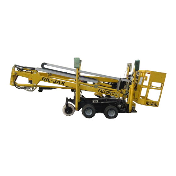
- Page 1 Service and Parts Manual AERIAL WORK PLATFORMS FALCON 125 Self Propelled Hydraulic Boom Lift B33-01-0083...
- Page 2 BOOM PERSONNEL LIFT This equipment is designed and manufactured in compliance with the duties, re- sponsibilities, and standards set forth for manufacturers in the ANSI 92.5 standard in effect at the time of manufacture. This equipment will meet or exceed applicable OSHA codes and ANSI A92.5 stan- dards when used in accordance with sections 5, 6, 7, 8, 9, &...
-
Page 3: Table Of Contents
Table of Contents Preface......................... v Safety........................1-1 Introduction..................1-1 Maintenance Safety................1-2 General Maintenance..............1-2 Battery Maintenance...............1-3 Damaged Equipment Policy ...............1-3 Safety Statement ................1-3 Damage Policy................1-3 Damage Repair Notice..............1-3 Introduction.....................2-1 General Description ................2-1 Specifications..................2-2 Boom Lift Work Platform ..............2-2 Warranty .....................2-3 Maintenance ....................3-1 Scheduled Service Checks ..............3-1 Daily/Weekly Service Checks ............3-1 Monthly Service Checks..............3-2 Lubrication..................3-3... - Page 4 Troubleshooting....................4-1 Troubleshooting ................. 4-1 Troubleshooting Flowcharts ............4-1 Troubleshooting Flowcharts .............. 4-5 Gasoline Engine Will Not Turn Over ..........4-6 Gasoline Engine Turns Over But Will Not Start ......4-7 Electric Motor Will Not Start ............4-8 Electric Motor Will Not Stay Running .......... 4-9 Green Light Does Not Turn On When Outriggers Are Down..
- Page 5 List of Illustrations Figure 3-1. Hydraulic Reservoir Breather/Dipstick...........3-4 Figure 3-2. Return Filter Assembly ................3-5 Figure 3-3. Ground Station Flow Controls ..............3-7 Figure 3-4. Upper Beam Lowering Flow Control Valve ...........3-8 Figure 3-5. Lower Beam Lowering Flow Control Valve...........3-9 Figure 3-6. Boom Rotate Flow Control Valves ............3-10 Figure 3-7.
- Page 6 List of Tables Table 2-1. Specifications ..................2-2 Table 3-1. Daily/Weekly Service Checks..............3-1 Table 3-2. Monthly Service Checks ................ 3-2 Table 3-3. Cylinder Operating Speeds, Factory Settings......... 3-6 Table 3-4. Hydraulic Pressure, Factory Settings ........... 3-12 Table 4-1. Electrical Components – Functional Description ........4-2 Table 4-2.
-
Page 7: Preface
PREFACE The purpose of this manual is to provide a thorough understanding of the Falcon 125 Self Propelled Hydraulic Boom Lift operation and controls. Read the safety and operating instructions in this manual and become familiar with the location and use of all controls. -
Page 9: Safety
The information contained herein is not to be considered as legal advice and is intended for informational purposes only. This information is offered to alert Bil-Jax customers procedures that may be of concern to them. This information is not intended to be all inclusive and is to be followed in the use of Bil-Jax equipment only. -
Page 10: Maintenance Safety
ALWAYS use static discharge prevention mats and ground- ing devices when handling electronic components. • NEVER tamper with cylinder load holding valves. Contact the Bil-Jax Service Department at 419.445.9675 if the cylinder load holding valves need adjusting. •... -
Page 11: Battery Maintenance
Federal OSHA and ANSI codes and regulations. Damage Policy There may be occasions when a Bil-Jax lift is involved in an incident that results in struc- tural damage to the lift. This can seriously compromise the ability of the lift to perform in a safe manner. - Page 12 FALCON 125...
-
Page 13: Introduction
Manual boom rotation is enabled from the ground by opening a valve and pushing the boom around the boom rotation centerline. The Falcon 125 boom lift, extension, and outrigger cylinders will not rust or corrode dur- ing storage since the cylinder rod is fully immersed in oil. It is important that the cylinder rods be kept clean and undamaged for the protection of the cylinder head packings. -
Page 14: Specifications
FALCON 125 SPECIFICATIONS Boom Lift Work Platform Model Number: Falcon 125 Serial Number ________________ Manufactured by: Bil-Jax, Inc. 125 Taylor Parkway Archbold, Ohio 43502 419.445.9675 Table 2-1. Specifications Feature Data Gross Vehicle Weight 3112 lbs (1412 kg) Rated Platform Load 300 lbs (135 kg) total or 1 occupant plus 120 lbs (44.8 kg) -
Page 15: Warranty
2 — INTRODUCTION WARRANTY Bil-Jax warrants its boom lifts for one year from the date of delivery against all defects of material and workmanship, provided the unit is operated and maintained in compliance with Bil-Jax’s operating and maintenance instructions. Bil-Jax will, at its option, repair or replace any unit or component part which fails to function properly in normal use. - Page 16 FALCON 125...
-
Page 17: Maintenance
Maintenance SCHEDULED SERVICE C HECKS Daily/Weekly Service Checks Perform the following daily/weekly service checks as listed in Table 3-1 Table 3-1. Daily /Weekly Service Chec Daily Service Check before use Weekly Check to see that all decals are present. Check that controls and indicators at ground and basket control stations operate properly. -
Page 18: Monthly Service Checks
FALCON 125 Monthly Service Checks Perform the following monthly service checks as listed in Table 3-2. Table 3-2. Monthly Service Checks Every Every Every Service Check month 6 months 12 months Check/add hydraulic oil per paragraph 3-3. Check hydraulic hoses, lines, and fittings per paragraph 3-3. -
Page 19: Lubrication
3 — MAINTENANCE LUBRICATION Lubrication makes operation of the Falcon 125 Boom Lift more efficient and extends the equipment life. All grease fittings on the Falcon 125 Boom Lift are labeled LUBRICATE WEEKLY with NLGI Grade 2 multi-purpose grease. There are 20 grease fittings. At each grease fit- ting, wipe off any dirt and grease residue and add approximately ½... -
Page 20: Fluid Check And Replacement
FALCON 125 Fluid Check and Replacement Remove the chassis cover plate to access the hydraulic reservoir, Figure 3-1. The hydrau- lic oil level should be checked with the oil warm and the engine off. Hydraulic cylinders should be retracted, the boom down and the outriggers raised. -
Page 21: Return Filter Replacement
3 — MAINTENANCE Return Filter Replacement The hydraulic oil filter should be replaced yearly or whenever filter contamination has a noticeable effect on the beam lift functions. If return filter clogging is suspected, check the system hydraulic pressure. With gas engine at full speed and no controls actuated, hydraulic system pressure should be near 0 (zero), or minimal. -
Page 22: Bleeding Air From Hydraulic System
FALCON 125 Bleeding Air From Hydraulic System Delayed response or sporadic outrigger or beam lift motions may indicate air in the cyl- inders. Use the following procedure to bleed entrapped air from the hydraulic system. Fill the reservoir with the proper hydraulic fluid. Replace, but do not tighten the reservoir fill cap. -
Page 23: Figure 3-3. Ground Station Flow Controls
If you suspect the flow rate is out of adjustment it is recommended that you contact the Bil-Jax Service Department at 419.445.9675 before proceeding. Changing the setting of this valve will affect the operation of every hydraulic cylinder on the boom lift. -
Page 24: Figure 3-4. Upper Beam Lowering Flow Control Valve
FALCON 125 Adjusting Beam Lowering Speed, Upper Beam A flow control valve at the upper beam lift cylinder (Figure 3-4) regulates the beam low- ering speed. The recommended beam lowering speed is 20 to 25 seconds from a fully raised position. Faster speed settings may be desirable for experienced boom lift opera- tors. -
Page 25: Figure 3-5. Lower Beam Lowering Flow Control Valve
3 — MAINTENANCE Adjusting Beam Lowering Speed, Lower Beam A flow control valve at the lower beam lift cylinder (Figure 3-5) regulates the beam low- ering speed. The recommended beam lowering speed setting is 10 to 15 seconds from a fully raised position. -
Page 26: Figure 3-6. Boom Rotate Flow Control Valves
FALCON 125 Adjusting Boom Rotate Speed Flow control valves (Figure 3-6) on the upper and lower boom controls regulate the boom rotate speed; these are set independently. A slower rotating speed may be required from the basket station. The recommended boom rotate speed setting is 45 to 50 seconds from a full stop-to-stop rotation. -
Page 27: Figure 3-7. Basket Tilt Flow Control Valve
3 — MAINTENANCE Adjusting Basket Tilt Speed A flow control valve at the back of the upper control valves (Figure 3-7) regulates the basket tilt speed. The recommended basket tilt speed setting is listed in 25 to 30 seconds in the tilt back position. Faster basket tilt speed settings may be desirable for experienced boom lift operators. -
Page 28: Hydraulic Pressure Checks And Adjustments
FALCON 125 Hydraulic Pressure Checks and Adjustments Hydraulic pressures are set at the factory and should not be adjusted unless a hydraulic component has been replaced in the regulated circuit. A pressure test port (Figure 3-8) is located at the back of the ground station boom control valves. - Page 29 3 — MAINTENANCE Connect a hydraulic pressure gage to the pressure test port. Start the gasoline engine. Run the engine at 3/4 throttle for at least five minutes to warm the hydraulic oil to the normal operating temperature. WARNING The hydraulic pressure reading is taken by extending an outrigger hydraulic cyl- inder to maximum extension.
-
Page 30: Figure 3-9. Boom Lift Bypass Valve
FALCON 125 Check/Adjust Boom Lift Pressure Boom lift pressure is regulated by the ground boom controls bypass valve. The valve is located on the back side of the ground station boom controls (Figure 3-9). HEX WRENCH ADJUST SCREW BYPASS VALVE Figure 3-9. -
Page 31: Figure 3-10. Extend Bypass Valve
3 — MAINTENANCE If no other hydraulic pressures are to be checked, shut down the engine and re- move the pressure gage. NOTE: The boom rotate pressure is dependent on the boom lift pressure setting. If the boom lift pressure setting has changed, the boom rotate pressure should be checked. -
Page 32: Figure 3-11. Basket Tilt Bypass Valves
FALCON 125 Replace the seal ring and adjust screw cap. Do not over tighten adjust screw cap; you can damage the seal ring. Tighten only enough to prevent an oil leak. Start the gasoline engine. Set the throttle to the FAST position. - Page 33 3 — MAINTENANCE While standing outside the basket, activate the tilt lever to fully tilt the basket forward. While standing outside the basket, hold the basket tilt control forward forcing the bypass valve to open. If the pressure gage reading is 1740 psig [120 bar (12 000 kPa)] nominal, no adjustment is required.
-
Page 34: Adjust Boom Rotation Chain
FALCON 125 ADJUST BOOM ROTATION CHAIN The boom rotation chain should be checked at least once per year for proper adjustment and wear. If the boom does not respond quickly, or if rotation movement is jerky, the boom rotation chain may need adjusting. -
Page 35: Adjust Lift Vehicle Drive Chains
3 — MAINTENANCE ADJUST LIFT VEHICLE DRIVE CHAINS The primary and secondary drive chains should be checked at least once per year for ad- justment and wear. Excess slack in a primary drive chain will cause a “thump” when reversing drive direc- tion. -
Page 36: Check/Adjust Primary Drive Chain Tension
FALCON 125 If the chain deflection is more than 1/2 inch (12 mm), adjust the secondary drive chains as follows: Remove the drive wheels and chain covers on both sides of the machine. b. Loosen all four axle bracket hex nuts (Figure 3-14). -
Page 37: Figure 3-15. Motor Bracket Screws
3 — MAINTENANCE MOTOR BRACKET SCREWS PRIMARY DRIVE CHAIN Figure 3-15. Motor Bracket Screws Inside the chassis, at the base of the motor bracket, is a chain tension adjust screw and lock nut (Figure 3-16). g. Reach inside the chassis, loosen the lock nut, and turn the adjust screw out to increase tension in the primary drive chain. -
Page 38: Boom Rotation Bearings
Repeat the measurement in step 2. Record the measurement. If the difference between the measurements in step 2 and step 4 is greater than 1/4 inch (6,4 mm) the slew ring bearing should be replaced. Notify Bil-Jax for bearing replacement instructions or assistance. -
Page 39: Limit Switch Checks And Adjustments
3 — MAINTENANCE LIMIT SWITCH CHECKS AND ADJUSTMENTS Adjusting Boom Down Limit Switch When the upper and lower booms are retracted, the boom down limit switch is actuated. The boom down limit switch must be actuated to lower or raise the outriggers. The boom down limit switch should trip just before the lower boom seats on the chassis. -
Page 40: Adjusting Function Limit Switch
FALCON 125 Adjusting Function Limit Switch When the hydraulic function switch (valve lever) is moved to the BASKET/GROUND CONTROLS position, the function limit switch is actuated. The limit switch must be tripped to operate the boom controls. The switch lever must release when the hydraulic function switch is moved to the DRIVE or OUTRIGGERS position. -
Page 41: Material Safety Data Sheets
3 — MAINTENANCE MATERIAL SAFETY DATA SHEETS MATERIAL SAFETY DATA SHEET FOR LEAD ACID BATTERIES, WET, FILLED WITH ACID SECTION I: GENERAL INFORMATION Manufacturer’s Name: Crown Battery Mfg. Company EMERGENCY NO: 800 487-2879 Street Address: 1445 Majestic Drive 800 OIL-TANK City, State, Zip Fremont, Ohio 43420 Phone Number:... - Page 42 FALCON 125 MATERIAL SAFETY DATA SHEET FOR LEAD ACID BATTERIES, WET, FILLED WITH ACID (continued) ******************************************************************************************** ***** SECTION V -- HEALTH HAZARD DATA ******************************************************************************************** ***** Primary Routes of Entry: Inhalation: Skin: Ingestion: Health Hazards: Acute EYES, SKIN, RESPIRATORY SYSTEM & DIGESTIVE SYSTEM Chronic: EYES, SKIN, RESPIRATORY SYSTEM &...
- Page 43 3 — MAINTENANCE Hygienic Work Practices: 3-27...
- Page 44 FALCON 125 MATERIAL SAFETY DATA SHEET AW-46 HYDRAULIC OIL 1-SITE SPECIFIC INFORMATION 2-GENERAL INFORMATION TRADE NAME: AW-46 HYDRAULIC OIL EMERGENCY TELEPHONE NUMBERS: (517) 849-2144 CHEMICAL FAMILY: LUBRICATING OIL CAS NUMBER: MIXTURE: ISSUE DATE 12/15/96 HAZARDOUS INGREDIENTS: ---------------------------------------------------------------------------- CONTAINS NO INGREDIENTS NOW KNOWN TO BE HAZARDOUS AS DEFINED IN OSHA 29 CFR 1910.1000 AND OSHA 29 CFR 1910.1200.
- Page 45 3 — MAINTENANCE MATERIAL SAFETY DATA SHEET AW-46 HYDRAULIC OIL (continued) SPECIAL PROTECTION INFORMATION RESPIRATORY PROTECTION (SPECIFIC TYPE) NONE REQUIRED VENTILATION: NORMAL LOCAL EXHAUST: NORMAL MECHANICAL EXHAUST (GENERAL) PROTECTIVE GLOVES: OIL IMPERVIOUS GLOVES RECOMMENDED EYE PROTECTION: SAFETY GLASSES RECOMMENDED OTHER PROTECTIVE EQUIPMENT: NONE REQUIRED ---------------------------------------------------------------------------- SPECIAL INSTRUCTIONS SPECIAL LABELLING INSTRUCTIONS: NOT REQUIRED...
-
Page 47: Troubleshooting
Continue to answer the questions and perform the indicated actions in sequence until the problem is corrected. If you are not able to correct a problem using the troubleshooting flowcharts and aids, notify Bil-Jax. Reference Parts Lists When using the troubleshooting flowcharts, refer to Figure 4-1 for the location of electri- cal box components. -
Page 48: Table 4-1. Electrical Components - Functional Description
FALCON 125 Table 4-1. Electrical Components – Functional Description Component Functional Description C1, C2, C3 Capacitors To keep voltage at K2, K4, and K8 relay coils for 0.3 seconds while function switch is moved from DRIVE to BASKET/GROUND. D2 Diode Prevents discharge of C1 capacitor through H1 lamp to ground. - Page 49 4 — TROUBLESHOOTING Table 4-1. Electrical Components – Functional Description (continued) Component Functional Description S1, S7 Interrupts 12 volts to motor and engine run circuits when pushbutton Emergency Stop Switches is pressed. Pushbutton must be reset to restart motor or engine. S2, S8 Momentarily interrupts 12 volts to motor and engine run circuits Engine Stop Switches...
-
Page 50: Figure 4-1. Electrical Box Components
FALCON 125 TERMINAL BLOCK Figure 4-1. Electrical Box Components... -
Page 51: Troubleshooting
4 — TROUBLESHOOTING TROUBLESHOOTING FLOWCHARTS The following troubleshooting flowcharts list Falcon 125 equipment problems that may occur. For each problem statement, there is a separate flowchart to guide you through a troubleshooting procedure. Problem Statement Page No. Gasoline Engine Will Not Turn Over............ -
Page 52: Gasoline Engine Will Not Turn Over
FALCON 125 Gasoline Engine Will Not Turn Over Before Troubleshooting Verify the Following: 1. Engine Key Switch is ON. 2. Master Power Switch is ON. 3. E-Stop Switches are released (OFF). RECHARGE VOLTS 4. Function Switch is in DRIVE or... -
Page 53: Gasoline Engine Turns Over But Will Not Start
4 — TROUBLESHOOTING Gasoline Engine Turns Over But Will Not Start Before Troubleshooting Verify the Following: 1. Gasoline in tank. 2. Fuel Valve is OPEN. 3. Choke is ON. ENGINE 4. Throttle is set to FAST. ENGINE OIL LEVEL OIL. NOTE: Terminal designations in troubleshooting chart refer to terminal block X1 in the REPLACE... -
Page 54: Electric Motor Will Not Start
FALCON 125 Electric Motor Will Not Start WAIT 15 MINUTES FOR MOTOR TO COOL. PRESS LED LIT ELECTRIC RESET BUTTON ON ON THERMAL MOTOR THERMAL OVERLOAD OVERLOAD RELAY F1. RELAY RELAY TRIPS AGAIN MOTOR IS DEFECTIVE. HEAR MOTOR CHECK LED LIT... -
Page 55: Electric Motor Will Not Stay Running
4 — TROUBLESHOOTING Electric Motor Will Not Stay Running Before Troubleshooting Verify the Following: 1. Function Switch is in the DRIVE or OUTRIGGER position. 2. Boom is fully lowered. HEAR MOTOR CHECK CONTACTOR K1 CLOSE MOTOR CONTACTOR WHEN ENGINE START SWITCH S3 OR S9 IS PRESSED CHECK... -
Page 56: Green Light Does Not Turn On When Outriggers Are Down
FALCON 125 Green Light Does Not Turn On When Outriggers Are Down ARE ALL ALL RED OUTRIGGERS EXTEND OUTRIGGER DOWN AND OUTRIGGERS UNTIL LEDs UNDER RED LEDs GO OUT. LIT ? LOAD CHECK CHECK VOLTS AT OUTRIGGER TIMER RELAY K6 AND... -
Page 57: Alarm Sounds With Boom Lift Level
4 — TROUBLESHOOTING Alarm Sounds With Boom Lift Level NOTE: Unidentified terminal designations in troubleshooting chart refer to terminal block X1 in the chassis VOLTS AT CHECK TERMINAL WIRING. electrical box. 11 ? LEVEL VOLTS AT CHECK SENSOR K10 ALARM RELAY K9, LEVEL SENSOR GROUND TERMINAL... -
Page 58: Green Light Comes On But Goes Out
FALCON 125 Green Light Comes On But Goes Out HYDRAULIC FUNCTION SWITCH MOVE IN BASKET/GROUND HYDRAULIC FUNCTION POSITION BEFORE BOOM SWITCH FASTER. ENABLED INDICATOR (SEE NOTE) (GREEN LIGHT) WENT OUT DOES GREEN BOOM CHECK ENABLED INDICATOR BOOM ENABLE RELAY K4... -
Page 59: Basket Control Boom Function Fails
4 — TROUBLESHOOTING Basket Control Boom Function Fails NOTE: Unidentified terminal designations in the troubleshooting chart refer to ENGINE terminal block X1 in the chassis START OR MOTOR electrical box. ENGINE OR MOTOR. RUNNING EXTEND HYDRAULIC ALL OUTRIGGERS AND PUT FUNCTION SWITCH HYDRAULIC FUNCTION SWITCH IN BASKET/GROUND... -
Page 60: Ground Control Boom Function Fails
FALCON 125 Ground Control Boom Function Fails ENGINE START OR MOTOR ENGINE OR MOTOR. RUNNING EXTEND HYDRAULIC ALL OUTRIGGERS AND FUNCTION SWITCH PUT HYDRAULIC FUNCTION IN BASKET/GROUND SWITCH IN BASKET/GROUND CONTROLS CONTROLS POSITION. POSITION CHECK BOOM SOME OF THE LOWER CONTROLS ENABLE... -
Page 61: Boom Lift Functions Are Slow Or Erratic
4 — TROUBLESHOOTING Boom Lift Functions Are Slow Or Erratic CHECK HYDRAULIC SYSTEM PRESSURE BLEED AIR AT TEST PORT. FROM LIFT CYLINDER IS PRESSURE HYDRAULIC CIRCUIT. 2750 PSI (190 BAR) HYDRAULIC REPLACE SYSTEM PRESSURE HYDRAULIC SYSTEM 30 TO 50 PSI RETURN FILTER. -
Page 62: All Hydraulic Functions Fail
FALCON 125 All Hydraulic Functions Fail NOTE: Gas engine hydraulic pump and electric motor hydraulic pump are connected in parallel. If a check valve fails on one of the pumps, the hydraulic pressure from the opposite pump will drop off. -
Page 63: Hydraulic Drive Function Fails
4 — TROUBLESHOOTING Hydraulic Drive Function Fails DOES MOVE HYDRAULIC ANY DRIVE HYDRAULIC FUNCTION FUNCTION FUNCTION SWITCH SWITCH IN WORK TO DRIVE POSITION. DRIVE CHECK INSPECT CONTROL VALVE FOR DOES REPLACE DRIVE CHAINS. INTERNAL LEAKAGE. DRIVE FUNCTION FAILED DRIVE CHAINS ARE CHAINS IN PLACE REPLACE OR REPAIR FAIL IN BOTH... -
Page 64: Outrigger Function Fails
FALCON 125 Outrigger Function Fails STOP CHECK ENGINE AND FOR +12 VOLTS FROM PRESS OUTRIGGER OUTRIGGER ENABLE SWITCH S12 ENABLE SWITCH. TO ENABLE VALVE SOLENOID. CAN YOU HEAR CHECK SOLENOID GROUND OUTRIGGERS CIRCUIT. REPLACE FAILED ENABLE VALVE SOLENOID OR OUTRIGGERS ENGAGE ENABLE VALVE V3. -
Page 65: Boom Function Fails
4 — TROUBLESHOOTING Boom Function Fails CHECK ANY BOOM BASKET/GROUND SELECTOR HYDRAULIC VALVE V1/V2, AND BYPASS FUNCTIONS VALVE IN THE UPPER WORK CONTROL VALVE. CHECK UPPER AND LOWER CONTROL BOOM VALVES, CYLINDER, AND LIFT EMERGENCY LOWERING FUNCTIONS VALVES VE1 OR VE2 FOR WORK INTERNAL LEAKAGE. -
Page 66: Troubleshooting Aids
FALCON 125 TROUBLESHOOTING AIDS The level sensor (Figure 4-2) is located inside the lift vehicle chassis. The status of the level sensor is indicated by two LEDs. Table 4-2 defines the level sensor LEDs. Electrical and hydraulic diagrams are provided to assist in the troubleshooting of the boom lift. -
Page 67: Figure 4-3. Simplified Electrical Schematic
4 — TROUBLESHOOTING LOAD SENSORS PS1 - PS4 EMERGENCY LOWERING ENGINE START ENGINE START ENGINE STOP ENGINE STOP EMERGENCY EMERGENCY STOP STOP OUTRIGGERS LOWER CONTROLS ENABLE ENABLE Figure 4-3. Simplified Electrical Schematic 4-21... -
Page 68: Figure 4-4. Wiring Diagram
FALCON 125 white green brown black black blue brown Figure 4-4. Wiring Diagram, Sheet 1 of 2 4-22... - Page 69 4 — TROUBLESHOOTING Figure 4-4. Wiring Diagram, Sheet 2 of 2 4-23...
-
Page 70: Figure 4-5. Hydraulic Diagram
FALCON 125 Left Wheel Left Wheel To Basket Boom Controls Drive Motor Drive Control GROUND STATION BOOM CONTROLS Beam Extend/ Right Wheel Right Wheel Retract Drive Motor Drive Control Control Beam Ground Rotation Selector Control Valve Hydraulic Function Basket Switch... - Page 71 4 — TROUBLESHOOTING Basket Tilt Tilt Compensating BASKET BOOM CONTROLS Cylinder Cylinder Tilt Bypass 1740 psi (120 bar) From Ground Station Holding Boom Controls Valves Basket Boom Beam Extend/Retract Cylinder Tilt Extend/Retract Control Holding Valves Beam Extend Bypass Boom 1740 psi Rotation (120 bar) Beam Rotation Cylinder...
- Page 72 FALCON 125 4-26...
-
Page 73: Replacement Decals
B06-00-0419 EMERGENCY LOWERING (decal on hydraulic reservoir) B06-00-0420 WARNING: STAND CLEAR OF B06-00-0115 1500 WATT LOAD LIMIT OUTRIGGER… B 06-00-0161B BIL-JAX – LARGE LABEL B06-00-0421 Operating Instructions B06-00-0167 Caution Tape, Black and Yellow B06-00-0422 EMERGENCY ROTATION B06-00-0173 SAFETY HARNESS LANYARD... - Page 74 ATTACHMENT INSTRUCTIONS BEFORE • 15 Amp maximum circuit. POINT B06-00-0115 OPERATING AIF/RFC STAY CLEAR B06-00-0115 B06-00-0173 MACHINE © Bil-Jax, Inc. 2004 B06-00-0405 B06-00-0173 B06-00-0405 B06-00-0060 THIS PLUG 115 VOLT B06-00-0060 B06-00-0062 B06-00-0062 WARNING EMERGENCY LOWERING Stand clear of outrigger while it is being lowered.
- Page 75 5 — REPLACEMENT DECALS OPERATING INSTRUCTIONS FOR FALCON 125 IMPROPER USE OF THIS EQUIPMENT WILL RESULT IN SERIOUS INJURY OR DEATH. WARNING STOP THIS MACHINE MUST NOT BE OPERATED UNLESS YOU ARE COMPLETELY FAMILIAR WITH THE INSTRUCTIONS CONTAINED IN THE OPERATING MANUAL...
- Page 76 Alterations, modifications, or changes to this machine CAPACITY ........300 LB. without the written authorization of Bil-Jax, Inc. as well as MAXIMUM PLATFORM HEIGHT ..34 FT. 5 IN. any unauthorized adjustment of valves, disabling or WORK HEIGHT ........
-
Page 77: Figure 5-2. Decal Locations
5 — REPLACEMENT DECALS Figure 5-2. Decal Locations, Sheet 1 of 2... - Page 78 FALCON 125 0036 0192 0225 0068 0424 0062 CHASSIS, LEFT SIDE GROUND CONTROL STATION 0225 0417 0334 0418 0400 BASKET BOOM CONTROLS ELECTRIC MOTOR COVER 0036 0036 0036 0419 BASKET TILT CYLINDER UPPER BOOM LIFT CYLINDER Figure 5-2. Decal Locations, Sheet 2 of 2...
-
Page 79: Parts List
Parts List... -
Page 80: Chassis Drive Components
FALCON 125 CHASSIS DRIVE COMPONENTS Refer to Table 6-1 for the chassis drive components parts list. Figure 6-1. Chassis Drive Components... -
Page 81: Table 6-1. Chassis Drive Components Parts List
6 — PARTS LIST Table 6-1. Chassis Drive Components Parts List Item No. Part No. Description Adjust Plate, Secondary Drive Chains Flat Washer Hex Nut Hex Nut Cap Screw Backing Plate, Front Axle Cap Screw Front Axle Drive Sprocket, Primary Fender Washer Flat Washer Cap Screw... -
Page 82: Boom Rotation Components
FALCON 125 BOOM ROTATION COMPONENTS Refer to Table 6-2 for the boom rotation components parts list. 21, 21A Figure 6-2. Boom Rotation Components... -
Page 83: Table 6-2. Boom Rotation Components Parts List
6 — PARTS LIST Table 6-2. Boom Rotation Components Parts List Item No. Part No. Description Boom Rotation Weldment Thrust Bearing, Slew Sleeve Bearing, Slew Cap Screw Flat Washer Pivot Pin, Rotation Cylinder Axle Pin, Idler Sprocket Fender Washer Sleeve Bearing, Idler Sprocket Idler Sprocket Chain, Rotation Drive B40-00-0027... -
Page 84: Chassis Electrical And Hydraulics
FALCON 125 CHASSIS ELECTRICAL AND HYDRAULICS Refer to Table 6-3 for the chassis electrical and hydraulics parts list. Figure 6-3. Chassis Electrical and Hydraulics... -
Page 85: Table 6-3. Chassis Electrical And Hydraulics Parts List
6 — PARTS LIST Table 6-3. Chassis Electrical and Hydraulics Parts List Item No. Part No. Description Chassis Electrical Box (see Figure 6-22) Flat Washer Cap Screw Socket Head Cap Screw Lock Washer B02-00-0039 Return Filter Assembly B02-00-0032 Oil Filter Element (not shown) B02-00-0040 Breather/Dipstick Seal Washer, Hydraulic... -
Page 86: Electric Motor And Pump
FALCON 125 ELECTRIC MOTOR AND PUMP Refer to Table 6-4 for the electric motor and pump parts list. TO RESERVOIR Figure 6-4. Electric Motor and Pump... -
Page 87: Table 6-4. Electric Motor And Pump Parts List
6 — PARTS LIST Table 6-4. Electric Motor and Pump Parts List Item No. Part No. Description B01-07-0014 Motor, 110V, 1.5kW Grommet, Wire Grip Mounting Plate, Capacitor Flat Washer Cap Screw Capacitor Wire Tie Insulation Cap Screw Flat Washer Self Locking Hex Nut Motor Bracket Cap Screw Cap Screw... -
Page 88: Figure 6-4. Electric Motor And Pump
FALCON 125 ELECTRIC MOTOR AND PUMP Refer to Table 6-4 for the electric motor and pump parts list. TO RESERVOIR Figure 6-4. Electric Motor and Pump 6-10... - Page 89 6 — PARTS LIST Table 6-4. Electric Motor and Pump Parts List (continued) Item No. Part No. Description Adapter, M/M Hydraulic Hose Assembly, 43 in. x 3/8 in. ID Spiral Wrap Flange Adapter Hose Clamp Socket Head Cap Screw Flexible Hydraulic Hose 20 in.
-
Page 90: Gasoline Engine And Pump
FALCON 125 GASOLINE ENGINE AND PUMP Refer to Table 6-5 for the gasoline engine and pump parts list. TO RESERVOIR Figure 6-5. Gasoline Engine and Pump 6-12... -
Page 91: Table 6-5. Gasoline Engine And Pump Parts List
6 — PARTS LIST Table 6-5. Gasoline Engine and Pump Parts List Item No. Part No. Description B20-00-0014 Engine, Honda, 13 Horsepower Cap Screw (Honda engine component) Battery Cable, Negative B00-00-0146-4 Square Key Sleeve Bushing B00-00-0146-2 Coupling Half, Engine Shaft B00-00-0146-1 Damper, Coupling B00-00-0146-6 Self Locking Hex Nut B00-00-0146-7 Flat Washer... -
Page 92: Figure 6-5. Gasoline Engine And Pump
FALCON 125 GASOLINE ENGINE AND PUMP Refer to Table 6-5 for the gasoline engine and pump parts list. TO RESERVOIR Figure 6-5. Gasoline Engine and Pump 6-14... - Page 93 6 — PARTS LIST Table 6-5. Gasoline Engine and Pump Parts List (continued) Item No. Part No. Description Cap Screw (Honda engine component) Ground Cable, Engine to Chassis Flat Washer Cap Screw Self Locking Hex Nut Fender Washer Bushing, Rubber Isolation Mount, Rubber Self Locking Hex Nut Rectifier/Regulator, D21...
-
Page 94: Outriggers
FALCON 125 OUTRIGGERS Refer to Table 6-6 for the outriggers parts list. 8, 8A 10,10A Figure 6-6. Outriggers 6-16... -
Page 95: Table 6-6. Outriggers Parts List
6 — PARTS LIST Table 6-6. Outriggers Parts List Item No. Part No. Description Cap Screw Clamp Standoff Block, Hose B36-00-0041 Pivot Pin Flat Washer Cap Screw Grease Fitting B02-03-0025 Hydraulic Cylinder B02-13-0113 Seal Kit, Cylinder Adapter, M/M Hydraulic Hose Assembly, Rear Outriggers, 110 in. -
Page 96: Lower Boom Components
FALCON 125 LOWER BOOM COMPONENTS Refer to Table 6-7 for the lower boom components parts list. 34, 34A Figure 6-7. Lower Boom Components 6-18... -
Page 97: Table 6-7. Lower Boom Components Parts List
6 — PARTS LIST Table 6-7. Lower Boom Components Parts List Item No. Part No. Description Beam Weldment Machine Screw, Flat Head Clamp B30-00-0054 Washer, Nylon Cap Screw Clamp Plate Standoff Block, Hose B04-07-0124 Retaining Ring Cotter Key Retaining Ring Cotter Key B36-00-0046 Pivot Pin... -
Page 98: Upper Boom Components
FALCON 125 UPPER BOOM COMPONENTS Refer to Table 6-8 for the upper boom components parts list. 4 5 3 1, 1A 16, 16A Figure 6-8. Upper Boom Components 6-20... -
Page 99: Table 6-8. Upper Boom Components Parts List
6 — PARTS LIST Table 6-8. Upper Boom Components Parts List Item No. Part No. Description Hydraulic Cylinder, Compensating Seal Kit, Compensating Cylinder B02-13-0115 Retaining Ring B04-07-0124 Cotter Key Grease Fitting Retaining Ring B04-07-0126 Washer, Nylon B30-00-0055 Pivot Pin B36-00-0049 Vertical Boom Weldment Cap Screw Flat Washer... -
Page 100: Boom Extension Components
FALCON 125 BOOM EXTENSION COMPONENTS Refer to Table 6-9 for the boom extension components parts list. 1, 1A 15, 15A 4 3 2 Figure 6-9. Boom Extension Components 6-22... -
Page 101: Table 6-9. Boom Extension Components Parts List
6 — PARTS LIST Table 6-9. Boom Extension Components Parts List Item No. Part No. Description Hydraulic Cylinder, Upper Beam Extension B02-13-0115 Seal Kit, Extension Cylinder Cap Screw Flat Washer B04-07-0128 Flange, Cylinder Mount Machine Screw, Flat Head B31-00-0045 Wear Pad, Side Extension Beam Grease Fitting Cotter Key... -
Page 102: 6-10 Troughs, Trough Covers, And Supports
FALCON 125 6-10 TROUGHS, TROUGH COVERS, AND SUPPORTS Refer to Table 6-10 for the troughs, trough covers, and supports parts list. Figure 6-10. Troughs, Trough Covers, and Supports 6-24... -
Page 103: Table 6-10. Troughs, Trough Covers, And Supports Parts List
6 — PARTS LIST Table 6-10. Troughs, Trough Covers, and Supports Parts List Item No. Part No. Description B18-00-0166 Cover, Upper Hose Trough & Cover Hose Trough, Flexible B18-00-0165 Cover, Lower Hose Trough & Cover Cap Screw Lock Washer Rivet Lock Washer Cap Screw Hex Nut... -
Page 104: 6-11 Basket Components
FALCON 125 6-11 BASKET COMPONENTS Refer to Table 6-11 for the basket components parts list. 18,18A Figure 6-11. Basket Components 6-26... -
Page 105: Table 6-11. Basket Components Parts List
6 — PARTS LIST Table 6-11. Basket Components Parts List Item No. Part No. Description Upper Controls (see Figure 6-12) Cap Screw Lock Washer Wire Tie Footswitch Wire Harness, Basket to Chassis Adhesive Anchor, Wire Tie Flat Washer Cap Screw Rivet Footswitch Wire Harness, Basket Self Locking Hex Nut... -
Page 106: 6-12 Upper Controls
FALCON 125 6-12 UPPER CONTROLS Refer to Table 6-12 for the upper controls parts list. BOOM CONTROL VALVES Figure 6-12. Upper Controls 6-28... -
Page 107: Table 6-12. Upper Controls Parts List
6 — PARTS LIST Table 6-12. Upper Controls Parts List Item No. Part No. Description Housing Weldment, Upper Controls Cap Screw Flat Washer Cap Screw Flat Washer Audible Alarm Hex Nut Valve Assembly, Boom Control Self Locking Hex Nut Electrical Box, 115 Volt Accessory Outlet GFI Outlet, 115 Volt AC Machine Screw Master Power Switch, S5... -
Page 108: 6-13 Lower Control Station
FALCON 125 6-13 LOWER CONTROL STATION Refer to Table 6-13 for the lower control station parts list. DRIVE AND FUNCTION SWITCH CONTROL VALVES OUTRIGGER CONTROL VALVES GROUND STATION BOOM CONTROL VALVES 29 28 Figure 6-13. Lower Control Station 6-30... -
Page 109: Table 6-13. Lower Control Station Parts List
6 — PARTS LIST Table 6-13. Lower Control Station Parts List Item No. Part No. Description Guard, Drive Control Valves B01-03-0047 Limit Switch, Selector Valve Flat Washer Socket Head Cap Screw Valves Assembly, Drive and Function Switch Valves Assembly, Outrigger Control Cotter Pin Self Locking Hex Nut Clevis Pin... -
Page 110: Figure 6-13. Lower Control Station
FALCON 125 6-13 LOWER CONTROL STATION Refer to Table 6-13 for the lower control station parts list. DRIVE AND FUNCTION SWITCH CONTROL VALVES OUTRIGGER CONTROL VALVES GROUND STATION BOOM CONTROL VALVES 29 28 Figure 6-13. Lower Control Station 6-32... - Page 111 6 — PARTS LIST Table 6-13. Lower Control Station Parts List (continued) Item No. Part No. Description B02-04-0079 Valve, Directional, Upper/Lower Controls Socket Head Cap Screw B02-00-0041 Manifold, 1 Position Flat Washer Machine Screw Edge Trim 27 in. Label Plate Cap Screw Flat Washer Guard, Boom Control Valves...
-
Page 112: 6-14 Chassis Covers And Panels
FALCON 125 6-14 CHASSIS COVERS AND PANELS Refer to Table 6-14 for the chassis covers and panels parts list. 5,5A Figure 6-14. Chassis Covers and Panels 6-34... -
Page 113: Table 6-14. Chassis Covers And Panels Parts List
6 — PARTS LIST Table 6-14. Chassis Covers and Panels Parts List Item No. Part No. Description Cover, Motor Cap Screw Flat Washer Cover Plate, Chassis Chain Guard, Right Hand Chain Guard, Left Hand Dust Cover Dust Cover Flat Washer Self Locking Hex Nut Flat Washer Inspection Cover... -
Page 114: 6-15 Rotation Hydraulics
FALCON 125 6-15 ROTATION HYDRAULICS Refer to Table 6-15 for the rotation hydraulics parts list. 1, 1A Figure 6-15. Rotation Hydraulics 6-36... -
Page 115: Table 6-15. Rotation Hydraulics Parts List
6 — PARTS LIST Table 6-15. Rotation Hydraulics Parts List Item No. Part No. Description Hydraulic Cylinder B02-13-0112 Seal Kit, Cylinder Elbow Fitting, 90° M/F Hydraulic Hose Assembly, 45 in. x 1/4 in. ID Adapter, M/M Port Plug Holding Valve Valve, Flow Control Fitting, Tee Elbow Fitting, 90°... -
Page 116: 6-16 Outrigger And Drive Hydraulics
FALCON 125 6-16 OUTRIGGER AND DRIVE HYDRAULICS Refer to Table 6-16 for the outrigger and drive hydraulics parts list. DRIVE AND FUNCTION SWITCH CONTROL VALVES OUTRIGGER CONTROL VALVES B L U Y E L / G N R E D... -
Page 117: Table 6-16. Outrigger And Drive Hydraulics Parts List
6 — PARTS LIST Table 6-16. Outrigger and Drive Hydraulics Parts List Item No. Part No. Description Pressure Tap Adapter, F/F Tee Fitting, F/M/M Hydraulic Hose Assembly, 79 in. x 3/8 in. ID Hydraulic Hose Assembly, 24 in. x 1/4 in. ID Elbow Fitting, 90°... -
Page 118: 6-17 Boom Control Hydraulics, Ground
FALCON 125 6-17 BOOM CONTROL HYDRAULICS, GROUND Refer to Table 6-17 for the boom control hydraulics parts list. BOOM CONTROL VALVES Figure 6-17. Boom Control Hydraulics, Ground 6-40... -
Page 119: Table 6-17. Boom Control Hydraulics, Ground Parts List
6 — PARTS LIST Table 6-17. Boom Control Hydraulics, Ground Parts List Item No. Part No. Description Adapter, M/M Elbow Fitting, 90° M/F Hydraulic Hose Assembly, 256 in. x 3/16 in. ID Hydraulic Hose Assembly, 112 in. x 3/16 in. ID Hydraulic Hose Assembly, 256 in. -
Page 120: 6-18 Boom Control Hydraulics, Basket
FALCON 125 6-18 BOOM CONTROL HYDRAULICS, BASKET Refer to Table 6-18 for the boom control hydraulics parts list. BOOM CONTROL VALVES Figure 6-18. Boom Control Hydraulics, Basket 6-42... -
Page 121: Table 6-18. Boom Control Hydraulics, Basket Parts List
6 — PARTS LIST Table 6-18. Boom Control Hydraulics, Basket Parts List Item No. Part No. Description Adapter, M/M Hydraulic Hose Assembly, 549 in. x 3/16 in. ID Hydraulic Hose Assembly, 379 in. x 3/16 in. ID Hydraulic Hose Assembly, 590 in. x 3/16 in. ID Hydraulic Hose Assembly, 379 in. -
Page 122: 6-19 Lower Boom Hydraulics
FALCON 125 6-19 LOWER BOOM HYDRAULICS Refer to Table 6-19 for the lower boom hydraulics parts list. Figure 6-19. Lower Boom Hydraulics 6-44... -
Page 123: Table 6-19. Lower Boom Hydraulics Parts List
6 — PARTS LIST Table 6-19. Lower Boom Hydraulics Parts List Item No. Part No. Description B02-04-0071 Load Holding Valve B02-04-0072 Emergency Lowering Valve B01-08-0015 Lowering Valve Spool B01-09-0101 Connecting Plug Adapter, M/M Tee Fitting, M/M/F Elbow, 90° M/F Hydraulic Hose Assembly, 549 in. x 3/16 in. ID Hydraulic Hose Assembly, 82 in. -
Page 124: 6-20 Upper Boom Hydraulics
FALCON 125 6-20 UPPER BOOM HYDRAULICS Refer to Table 6-20 for the upper boom hydraulics parts list. Figure 6-20. Upper Boom Hydraulics 6-46... -
Page 125: Table 6-20. Upper Boom Hydraulics Parts List
6 — PARTS LIST Table 6-20. Upper Boom Hydraulics Parts List Item No. Part No. Description Elbow, 90° M/F Adapter, M/M Spiral Wrap Hydraulic Hose Assembly, 379 in. x 3/16 in. ID Hydraulic Hose Assembly, 382 in. x 3/16 in. ID Hydraulic Hose Assembly, 258 in. -
Page 126: 6-21 Drive Hydraulics
FALCON 125 6-21 DRIVE HYDRAULICS Refer to Table 6-21 for the drive hydraulics parts list. Figure 6-21. Drive Hydraulics 6-48... -
Page 127: Table 6-21. Drive Hydraulics Parts List
6 — PARTS LIST Table 6-21. Drive Hydraulics Parts List Item No. Part No. Description Banjo Screw, Hydraulic Seal Washer, Hydraulic Banjo Fitting Spiral Wrap Hydraulic Hose Assembly, 87 in. x 3/86 in. ID Elbow, 90° M/F Adapter, M/M Hydraulic Hose 12 in. -
Page 128: 6-22 Chassis Electrical Box Components
FALCON 125 6-22 CHASSIS ELECTRICAL BOX COMPONENTS Refer to Table 6-22 for the chassis electrical box components parts list. 3, 3A Figure 6-22. Chassis Electrical Box Components 6-50... -
Page 129: Table 6-22. Chassis Electrical Box Components Parts List
6 — PARTS LIST Table 6-22. Chassis Electrical Box Components Parts List Item No. Part No. Description B01-10-0251 Capacitor, C1, C3 (63V / 1000) B01-06-0050 Relay, K5 B01-06-0048 Relay K2-K4 B01-06-0049 Relay Socket, K2-K4 B01-10-0249 Power Supply, 110V-12V DC Capacitor, C2 (63V / 47μF) Contactor, K1 B01-06-0046 B01-06-0047... -
Page 130: Pushbutton Panel Components, Ground Station
FALCON 125 6-23 PUSHBUTTON PANEL COMPONENTS, GROUND STATION Refer to Table 6-23 for the ground station pushbutton panel parts list. Wire to Directional Valve White from Level Sensor Wire to Directional Valve Figure 6-23. Ground Station Pushbutton Panel Components Table 6-23. Ground Station Pushbutton Panel Parts List Item No. -
Page 131: Pushbutton Panel Components, Basket Station
6 — PARTS LIST 6-24 PUSHBUTTON PANEL COMPONENTS, BASKET STATION Refer to Table 6-24 for the basket station pushbutton panel parts list. Figure 6-24. Basket Station Pushbutton Panel Components Table 6-24. Basket Station Pushbutton Panel Parts List Item No. Part No. Description B01-10-0226 Switch, Outriggers Enable Pushbutton... - Page 132 FALCON 125 6-54...
-
Page 133: Ansi Reprint
ANSI Reprint The following sections are reprinted from the ANSI A92.5-1992 code in effect at the tim of manufacture. Permission t o reprint has been granted by the Scaffold Industry Association. Responsibilities of Dealers Basic Principles Sound principles of safety, training, inspection, maintenance, ap- plication, and operation consistent with all data available regarding the parameters of intended use and expected environment shall be applied in the training of opera- tors, i... - Page 134 FALCON 125 5.8 Assistance to Owners and Users If a dealer is unable to answer an owner's or user's question relating to rated capacity, intended use, maintenance, repair, inspec- tion, or operation of the aerial platform, the dealer shall obtain the proper informa- tion from the manufacturer and provide that information to the owner or user.
- Page 135 7 — ANSI REPRINT The inspection shall be made by a person qualified as a mechanic on the specific make and model of the aerial platform. The inspection shall include all items speci- fied by the manufacturer for a frequent inspection and shall include but not be lim- ited to the following: a) All functions and their controls for speed(s), smoothness, and limits of motion.
- Page 136 FALCON 125 6.11 Operation When an owner operates an aerial platform, he shall have the responsi- bilities of uses as specified in section 7 of this standard and his operating personnel shall have responsibilities of operators as specified in section 8 of this standard.
- Page 137 7 — ANSI REPRINT 7.3.2 Annual Inspection An inspection as outlined in section 6.6 of this standard shall be conducted. 7.3.3 Pre-start Inspection Before use each day or at the beginning of each shift, the aerial platform shall be given a visual inspection and functional test including but not limited to the following: a) Operating and emergency controls.
- Page 138 FALCON 125 7.7 Before Operation Before authorizing an operator to operate an aerial platform, the user shall ensure that the operator has: a) Been instructed by a qualified person in the intended purpose and function of each control. b) Read and understood the manufacturer's operating instruction(s) and users safety rules, or been trained by a qualified person on the contents of the manu- facturer's operating instruction(s) and users safety rules.
- Page 139 7 — ANSI REPRINT 7.10 Hazardous Locations It shall be the responsibility of the user to determine the hazard classification of any particular atmosphere or location according to ANSI/NFPA 505-1987. 7.10.1 Hazardous Locations Aerial platforms operated in hazardous locations shall be approved and of the type required by ANSI/NFPA 505-1987. 7.11 Warnings and Instruction The user shall direct his operating personnel and su- pervise their work to ensure operation of the aerial platform in compliance with this standard.
- Page 140 FALCON 125 7.11.15 Stunt Driving Stunt driving and horseplay shall not be permitted. 7.11.16 Unauthorized Use Means shall be used to protect against use by unau- thorized person(s). 7.12 Operation of the Aerial Platform If a user is also the operator of an aerial plat-...
- Page 141 7 — ANSI REPRINT 8.3 Pre-start Inspection Before use each day or at the beginning of each shift, the ae- rial platform shall be given a visual inspection and functional test including but not limited to the following: a) Operating and emergency controls. b) Safety devices.
- Page 142 FALCON 125 d) Overhead obstructions and high voltage conductors. e) Hazardous locations. f) Inadequate surface and support to withstand all load forces imposed by the ae- rial platform in all operating configurations. g) Wind and weather conditions. h) Presence of unauthorized persons.
- Page 143 7 — ANSI REPRINT 8.10.4 Reporting Potentially Hazardous Locations The operator shall immedi- ately report to his supervisor any potentially hazardous location(s) (environment) which become evident during operation. 8.10.5 Altering Safety Devices Altering or disabling of interlocks or other safety devices shall be prohibited.
- Page 144 FALCON 125 8.11 Assistance to Operator If an operator encounters any suspended malfunction of the aerial platform, or any hazard or potentially unsafe condition relating to capac- ity, intended use or safe operation, he shall cease operation of the aerial platform and request further information as to safe operation from his management, or the owner, dealer, or manufacturer before further operation of the aerial platform.
- Page 145 7 — ANSI REPRINT M.S.A.D. = Minimum Safe Approach Distance (See Table 7-1) Figure 7-1. Minimum Safe Approach Distance (M.S.A.D.) • Do not allow machine, personnel, or conductive materials inside prohibited zone. • Maintain M.S.A.D. from all energized lines and parts as well as those shown. •...
-
Page 146: Table 7-1. Minimum Safe Approach Distance (M.s.a.d.) To Energized
FALCON 125 Table 7-1. Minimum Safe Approach Distance (M.S.A.D.) to energized (exposed or insulated) power lines and parts. Minimum Safe Approach Distance Voltage Range (Feet) (Meters) (Phase to Phase) 0 to 300V Avoid Contact Over 300V to 50KV 3.05 Over 50KV to 200KV 4.60... - Page 148 125 Taylor Parkway Archbold, OH 43502 Phone (419) 445-9675 (800) 527-5333 (419) 445-0367...
Need help?
Do you have a question about the FALCON 125 and is the answer not in the manual?
Questions and answers