General Air Products Vapor Pipe Shield VPS-500A Installation, Operation And Maintenance Manual
Hide thumbs
Also See for Vapor Pipe Shield VPS-500A:
- Installation, operation and maintenance manual (32 pages) ,
- Maintenance manual (7 pages)
Table of Contents
Advertisement
Quick Links
Vapor Pipe Shield
™
ENGINEERED VAPOR-PHASE CORROSION INHIBITOR SYSTEMS
For Dry Pipe & Pre-Action Fire Sprinkler Systems
Installation, Operation, and
Maintenance Manual
Models: VPS-500A / VPS-1000A / VPS-1500A / VPS-2000A
Technical Assistance:
800-345-8207
Additional Product Information:
generalairproducts.com
Version 1.8
Dec.-2022
Advertisement
Table of Contents

Related Manuals for General Air Products Vapor Pipe Shield VPS-500A

Summary of Contents for General Air Products Vapor Pipe Shield VPS-500A
- Page 1 Vapor Pipe Shield ™ ENGINEERED VAPOR-PHASE CORROSION INHIBITOR SYSTEMS For Dry Pipe & Pre-Action Fire Sprinkler Systems Installation, Operation, and Maintenance Manual Models: VPS-500A / VPS-1000A / VPS-1500A / VPS-2000A Technical Assistance: 800-345-8207 Additional Product Information: generalairproducts.com Version 1.8 Dec.-2022...
-
Page 2: Table Of Contents
Version 1.8 Dec.-2022 ABLE OF ONTENTS Safety Guidelines & Disclosures ................................3 Overview ........................................4 Installation ........................................ 5 Location ......................................5 Mounting ......................................6 Flow Reversal (Field Retrofit)..............................9 Inlet Connections ..................................10 Outlet Connections ..................................10 Drain Connections ..................................11 VPS Purge Valve ................................... -
Page 3: Safety Guidelines & Disclosures
VPS unit. System fill time must be checked for compliance with NFPA standards after installation. For more information, contact General Air Products Technical Assistance at (800) 345-8207 for assistance as needed. -
Page 4: Overview
Version 1.8 Dec.-2022 VERVIEW Vapor Pipe Shield (VPS) was created to be an economical & scalable option to protect various sizes of dry-pipe sprinkler systems, and is easily upgradable to handle later-date expansions of existing systems. Sizing and capacity information for VPS variants are displayed in the table below. Model System Installed... -
Page 5: Installation
Version 1.8 Dec.-2022 Vapor Pipe Shield is intended for the exclusive use with properly-sized General Air Products’ Fire- Protection Air Compressors. Use with alternative equipment may not have been verified by the Manufacturer and may void Manufacturer’s Warranty. NSTALLATION 3.1 L OCATION Install the Vapor Pipe Shield (VPS) unit in a clean, dry location;... -
Page 6: Mounting
Shutoff Valve (sold separately) is strongly recommended to be placed before the VPS unit. Contact General Air Products Technical Assistance at (800) 345-8207 for assistance as needed. If the VPS unit is to be placed before the other corrosion mitigation equipment, NOTICE contact the corrosion mitigation equipment’s manufacturer first to confirm such... - Page 7 Version 1.8 Dec.-2022 CAUTION While the VPS unit creates no vibration, failure to properly secure the unit may result in damage to the system, unit, or personnel. Page | 7...
- Page 8 Version 1.8 Dec.-2022 Mount Upper Clamp. Push the top-most Module of the VPS unit into the Upper Clamp as shown. The jaws of the Upper Clamp should lock completely over the top-most Module. Note, the top- most Module will rest loosely inside the Upper Clamp.
-
Page 9: Flow Reversal (Field Retrofit)
Version 1.8 Dec.-2022 3.3 F EVERSAL IELD ETROFIT The Vapor Pipe Shield (VPS) unit can have its flow reversed by completing the following steps. If already installed, always uninstall the VPS unit prior to any field retrofit work. The standard configuration is shown in the adjacent figure. -
Page 10: Inlet Connections
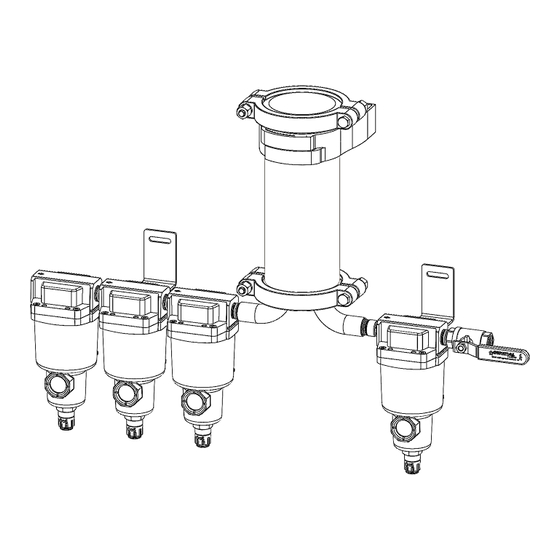
Version 1.8 Dec.-2022 3.4 I NLET ONNECTIONS The VPS inlet includes a water removal filter, followed by 2 coalescing filters, mounted in series on the lower corner of the unit. The inlet of the first filter is to be connected to the air source/ air storage tank. It’s strongly recommended that a Shutoff Valve (sold separately) be positioned directly before the VPS unit (between arrangement below. -
Page 11: Drain Connections
Version 1.8 Dec.-2022 3.6 D RAIN ONNECTIONS The VPS unit incorporates a built-in auto drain on each filter. These auto drains utilize 3/8” push to connect tube fittings, which are available for routing the drains to a desired location. A coil of 3/8” tubing is provided to connect to each Drain Port. -
Page 12: Vps Purge Valve
Version 1.8 Dec.-2022 3.7 VPS P URGE ALVE Purging of fire sprinkler piping system is optional with VPS. The corrosion inhibitor vapors will disperse throughout the piping system even without the aid of a purge valve. The initial filling of the sprinkler system piping to normal working pressure provides sufficient VPS Inhibitor to provide complete corrosion protection coverage to internal surfaces within approximately 21 days. - Page 13 Version 1.8 Dec.-2022 The VPS Purge Valve (optional) (sold separately), if utilized, must be set to the appropriate setting based on the table below. Select the maximum pressure the dry-pipe sprinkler system will be operating on, then the compressor flow rate. Where that column and row intersect on the chart is the numbered setting that the VPS Purge Valve should be set to.
- Page 14 Version 1.8 Dec.-2022 To adjust the Purge Setting, pull up lightly on the light-grey knob, and then turn in the +/- direction to adjust the numbered setting as shown below. One full turn will increase the numbered setting by one in either direction. Once set, lightly press the light-grey knob back in until it clicks back into place.
-
Page 15: Vps Vapor Indicator Test-Port
Version 1.8 Dec.-2022 3.8 VPS V APOR NDICATOR A VPS Vapor Indicator Test-Port (VIT) (included & optional) may be installed if desired. Also included are a set of Replaceable Indicator Cartridges (RIC) (included & optional) which may also be used if desired on the VIT. -
Page 16: Material Compatibility
The following materials have undergone testing to confirm compatibility with the Vapor Pipe Shield Product. Materials not shown may not have been verified by the manufacturer and may void warranty. Contact General Air Products Technical Assistance at (800) 345-8207 for more information in regards to material compatibility. -
Page 17: Start-Up Instructions
Version 1.8 Dec.-2022 TART NSTRUCTIONS With all the connections made as described in , the Vapor Pipe Shield “S 3; I – ( . 5)” ECTION NSTALLATION (VPS) unit is ready to start. The following measures should be undertaken anytime a VPS unit is installed. Depressurize the entire dry-pipe sprinkler system to atmosphere (0 PSIG). - Page 18 Version 1.8 Dec.-2022 Slowly open the inlet Shutoff Valve directly before the VPS unit, if utilized, to pressurize the VPS unit as shown in the diagram below. Note that while the air source pressurizes the VPS unit, the filters may temporarily purge air until enough pressure is built up to seal their respective Drain Ports.
-
Page 19: Theory Of Operation
HEORY OF PERATION 5.1 I NITIAL ILTRATION FILTERS Air is produced from an air source (for example from an air compressor) and is directed into the Pre- filters of the Vapor Pipe Shield (VPS) unit. The first pre-filter is a water removal filter, which removes large debris and bulk water from the airstream. -
Page 20: Maintenance Schedule
AINTENANCE CHEDULE The Vapor Pipe Shield (VPS) unit requires Packages Kit # Description Annual Maintenance, ideally when the sprinkler VPS-500A Includes Replacement Filter VPS-500-MKA system is inspected. Maintenance Kits are available Maintenance Kit Element(s) & Cartridge(s) with all necessary materials for each Annual VPS-1000A Includes Replacement Filter Maintenance Period. - Page 21 3) After the VPS unit is depressurized to atmospheric pressure (0 PSIG), open the Upper Clamp, and remove & separate each Module from the assembly. A 5/8” wrench can be used to remove all Bolted Clamps securing the Module(s), as shown in the adjacent figure.
- Page 22 7) If a Single Module (VPS-500) is used, take the 10” Module with the Cap; and with the cap-side up, line up the I/O Manifold’s inlet / outlet ports with the center of each of the Cartridge’s chambers. If Multiple Modules (VPS-1000 +) are used, stack the 8”...
- Page 23 10) If an Air Storage Tank(s) is present before the VPS unit, the Tank(s) should be completely drained of water prior to start, and ensure all fittings are installed and tightened properly. Failure to check all pressurized fittings may result in a potentially hazardous situation WARNING which COULD result in death or serious injury.
- Page 24 14) Once the pressurization of the VPS unit is complete, perform a leak test and fix any leaks found, then slowly open the VPS discharge Shutoff Valve, as shown in the diagram below. Failure to perform a leak test or check all parts & fittings for tightness may result in WARNING a potentially hazardous situation which COULD result in death or serious injury.
-
Page 25: Troubleshooting
ROUBLESHOOTING The following table describes several possible (but not all) troubleshooting scenarios with possible solutions that may be experienced over the life of Vapor Pipe Shield (VPS). Every system is unique with its own set of specific circumstances and unique characteristics. However, contaminants or other foreign materials within a sprinkler system may adversely impact the properties and performance of VPS, and may void manufacturer warranty. -
Page 26: General Arrangements
ENERAL RRANGEMENTS 8.1 S AMPLE YSTEM AYOUT NOT TO SCALE 8.2 F EATURE AYOUT Page | 26... -
Page 27: Maintenance Schedule Connections
8.3 M AINTENANCE CHEDULE ONNECTIONS Page | 27... -
Page 28: Module/ Cartridge Arrangement
8.4 M ODULE ARTRIDGE RRANGEMENT Page | 28... -
Page 29: General Arrangement
8.5 G ENERAL RRANGEMENT Page | 29... -
Page 30: Warranty Policy
OLICY GENERAL PROVISIONS & LIMITATIONS DISCLAIMER General Air Products, Inc. (the "Company") warrants to each original THE FOREGOING WARRANTY IS EXCLUSIVE AND IT IS EXPRESSLY purchaser ("Purchaser") of its new products from the Company or its AGREED THAT, EXCEPT AS TO TITLE, THE COMPANY MAKES NO...
Need help?
Do you have a question about the Vapor Pipe Shield VPS-500A and is the answer not in the manual?
Questions and answers