Table of Contents
Advertisement
Quick Links
Lithium-ion battery type
Operation Manual
TO THE OPERATOR AND THE PERSON IN CHARGE OF
MAINTENANCE AND CARE OF THE UNIT:
z Read this Manual carefully before operating the unit.
z Keep this Manual where it is readily accessible for reference when needed.
z This Manual describes operations of this unit and instructions on how to
operate the pulse oximeter and oxygen monitor. You may skip any section(s)
describing functions that are not included in your specific unit.
Equipment for neonatal and premature infants: Incubator
ORIGINAL
0123
Advertisement
Table of Contents

Related Manuals for Atom IncuArch


Summary of Contents for Atom IncuArch
- Page 1 Equipment for neonatal and premature infants: Incubator ORIGINAL 0123 Lithium-ion battery type Operation Manual TO THE OPERATOR AND THE PERSON IN CHARGE OF MAINTENANCE AND CARE OF THE UNIT: z Read this Manual carefully before operating the unit. z Keep this Manual where it is readily accessible for reference when needed. z This Manual describes operations of this unit and instructions on how to operate the pulse oximeter and oxygen monitor.
- Page 2 EU OFFICE Via Libia, 54 - 20081 Abbiategrasso (MI) - Italy Tel: +39 02 9466329 Fax: +39 02 9081428...
-
Page 3: Introduction
INTRODUCTION Thank you for purchasing IncuArch. This Operation Manual deals with the specifications, operation and maintenance of the IncuArch. Atom is by no means responsible for any malfunction arising from a user ignoring the instructions for operation and mainte- nance described in this Manual as well as any accident attributable to repair by someone other than technical personnel belonging to or authorized by Atom. - Page 4 3. Never use the unit if it is found to be defective. If any damage or malfunction of the unit should be noticed, stop using it immediately and contact your local Atom representative. 4. Follow the EMC information given in this Manual.
- Page 5 Definition of Symbols 1. Symbols to indicate danger, warning or caution Symbol Title and indication Caution:Withstand load Indicates that the use exceeding the indicated maximum load capacity (withstand load) may cause falling or damage of the unit. General attention Indicates unspecified general danger, warning or caution. Caution: Hot surface Indicates that the surface can be dangerously hot under certain conditions.
- Page 6 4. Symbols of international standards (IEC) Symbols Title and indication Type B applied part Indicates that the device is classified as Type B in terms of the degree of protection against elec- tric shock. See Operation Manual Follow Operation Manual. Type BF applied part Indicates that the device is classified as Type BF in terms of the degree of protection against electric shock.
- Page 7 5. Other symbols Symbol Title and indication Setting Indicates that a setting is increased. Setting Indicates that a setting is decreased. AC Power Indicates that the AC power is being supplied if an adjacent indicator is on. Indicates that the AC power is not being supplied if an adjacent indicator is off. Alarm Indicates that an audible alarm is silenced.
- Page 8 Symbol Title and indication Alarm Indicates the inability to detect pulse during measurement. (For Nellcor pulse oximeter) (Red marking) Alarm Indicates an alarm related to an oxygen sensor. Sensitivity setting indicator Indicates that the sensitivity mode is set to “Max”. (For Masimo pulse oximeter) Sensitivity setting indicator Indicates that the sensitivity mode is set to “APOD”.
- Page 9 If any abnormal condition or trouble should occur to the unit, indicate on the unit that it is out of order and contact your local Atom representative or service engineer immediately. If any abnormal condition or trouble should occur, do not use the unit until it has been repaired...
-
Page 10: Table Of Contents
Table of Contents INTRODUCTION [7] Oxygen Supply ......................Supplying Oxygen ......... 50 7-1. PLEASE READ WITHOUT FAIL 7-2. Using the Oxygen Monitor ......51 Calibrating the Oxygen Monitor ..51 7-2-1. [1] Safety Instructions ......... 7-2-2. Setting the Upper and Lower Alarm DANGER .......... - Page 11 [12] Alarms ..............[13] Troubleshooting ..........APPENDIX [14] Technical Data ..........[15] EMC Level and Classification ....
-
Page 12: Safety Instructions
Safety Instructions Safety Instructions Please follow the operating instructions described in this Manual to help ensure safe use of the unit. The unit should be operated only by those who have received relevant training and instruction regarding its opera- tion. The unit should only be operated according to its intended use. DANGER 1-1. -
Page 13: Warning
Safety Instructions Do not use ether, alcohol or any other flammable substances. Even a small amount of ether, alcohol or other flammable substances may cause a fire when mixed with the oxy- gen in the incubator. Analyze arterial gas levels repeatedly when a high oxygen environment is required. It has been reported that when setting the concentration of oxygen in the incubator to a high level, it is ex- tremely important and essential to repeatedly measure the oxygen concentrations inside the incubator and ana- lyze arterial blood gas in order to correctly maintain oxygen concentrations. - Page 14 If the battery is subjected to a shock, it may also cause smoke or fire. If it happens, stop using or recharging the battery, and contact your local Atom representative immediately.
- Page 15 In other cases such as where the unit belongs to an individual: Dispose of the battery according to the in- struction of your local government. If you are not sure how to dispose of the battery, contact your local Atom representative. Charge the battery as instructed.
-
Page 16: Caution
If the unit fails to operate correctly, stop using it immediately. Indicate on the incubator that it is out of order and contact your local Atom representative. Do not reuse the disposable safety bands. Change the disposable safety bands for every infant. Reusing them could lead to infection. - Page 17 A fire or electric shock may result, or the unit may malfunction. If a large amount of liquid has spilled on the unit, immediately wipe it up and call your local Atom representative to request checking of the internal elec- tronic circuit.
-
Page 18: Parts Identification
Parts Identification Parts Identification Main body 2-1. J Left side J Right side J Rear of the main body Name Name Admittance panel Snap-open access port Hood Oxygen sensor connection port Lighting lamp Skin temperature probe connection port Admittance panel latch Connector for SpO sensor Tube introduction slit... - Page 19 Parts Identification J Mattress Platform and Inside of Incubator Name Name Mattress Fan (common to both V-707 and V-808) Disposable safety band Heater Mattress platform Battery 1 Packing for main body Battery 2 (option) Middle board Battery cover...
-
Page 20: Operation Panel
Parts Identification Operation panel 2-2. Name Description Displays skin temperature, set temperature, SpO , pulse rate, oxygen Display area concentration, etc. Used to switch display screens or to specify various settings. Control switches Used to turn the light ON or OFF or to change brightness. Light switch Used to silence alarms. -
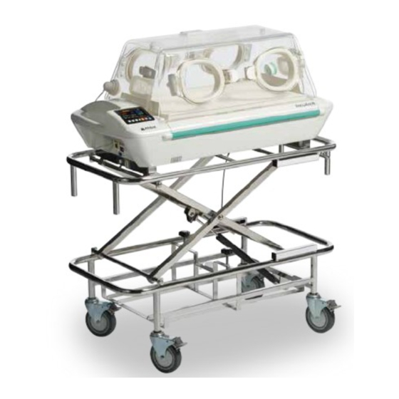
Page 21: Stands
Parts Identification 2-3. Stands J HL stand (option) Name HL stand Caster J Cabinet stand (option) Name Cabinet stand Caster... -
Page 22: Preparation Before Use
Preparation before Use Preparation before Use Assembly 3-1. Be sure to secure the incubator and a stand using the incubator retainer. Failure to do so may cause the incubator to tip over if a force is applied while the hood is open, or to fall due to shock received during transportation. -
Page 23: Adjusting The Hl Stand
Preparation before Use (2) Be sure that the rubber feet of the incubator are placed on the incubator retainer before tightening the lever of the retainer to secure the incubator. Incubator retainer Lever Adjusting the HL Stand 3-2. The HL stand is steplessly adjustable in height in a range from 48 to 80cm (from the bottom of the incubator to the floor). -
Page 24: Locking The Casters
Preparation before Use Locking the Casters 3-4. The casters of the HL stand and cabinet stand have locks. When using the incubator placed on the HL or cabinet stand, follow the procedure below to lock the casters: For HL Stand (Option) 3-4-1. -
Page 25: Securing The Unit To An Ambulance
Preparation before Use 3-5. Securing the Unit to an Ambulance When securing the unit using the HL stand, ensure that incubator is secured to the stand using the retainers. The unit must be loaded into an ambulance by at least two people. When using the HL stand, lower it to the lowest position before utilizing at least two people to lift the unit. -
Page 26: Power Requirements
Power requirements Power requirements The unit can operate from an AC power source (AC100-240V), built-in batteries or an external DC power source (DC12/24V). Whenever the power cord is not connected to a power outlet, or the power supply from an AC power source (AC100-240V) or an external DC power source (DC12/24V) is shut down, the power is automatically supplied from the built-in batteries. -
Page 27: Using An Ac Power Source (Ac100-240V)
Power requirements 4-2. Using an AC Power Source (AC100-240V) (1) Connect the power cord to the AC inlet on the AC inlet right side of the main body. Then connect the pow- er plug on the other end of the power cord to a power outlet. - Page 28 (4) Remove the old fuse and replace it with a new one. (5) Push the fuse box back into place. (6) Reconnect the power cord to the AC inlet. z If the replaced fuse blows out again, stop using the incubator and contact your local Atom repre- sentative.
-
Page 29: Using The Built-In Battery Power Supply
(AC100-240V) or an external DC source (DC12V/24V) is not available. Operate the unit using an AC source whenever possible. The IncuArch is a transport infant incubator that can operate on built-in batteries. With fully charged non-degraded batteries, the unit operates for approximately 180 minutes after the in- cubator temperature has been stabilized under conditions in which the incubator temperature is 36°C and ambient temperature is 15°C. - Page 30 An indicator is lit Symbol surrounded tery has no remaining charge. connected by a dotted line Battery has a defect. Turn off the power switch and An indicator is lit Battery failure contact your local Atom repre- A red frame sentative.
- Page 31 Power requirements Indicator Indication Name Charging status of battery The battery is charging. Remaining Indicators are lit A white frame The batter y level is somewhat battery level 3 A white frame alternately with a charg- low. (charging) with 3 lit cells ing symbol The battery is charging.
- Page 32 Power requirements J Battery drain and indication when only battery 1 is used and when two batteries (1 and 2) are used If only “Battery 1” is used: If both “Battery 1” and “Battery 2” are used: When the remaining bat- The power charged in “Battery 1”...
-
Page 33: Using An External Dc Power Source (Dc12V/24V)
When using a connection cable, verify that it complies range with the requirements listed in the table on the right be- Maximum fore contacting your local Atom representative. 6.5A current z A cigarette lighter socket in an ambulance does not provide adequate external DC voltage. So, do not use it as a terminal point for connection cable. - Page 34 Power requirements (2) Plug the connection cable into the DC power con- External DC power inlet nection port and turn the ring to firmly secure the cable. Ring (3) Press the switch on the control panel to turn the power on. Power is supplied and the unit be- gins operating.
- Page 35 To avoid failures, wait for at least one minute or so after the breaker has been tripped, and then push the bottom. z If the reset breaker is tripped again, stop using it and contact your local Atom representative.
-
Page 36: Display Screens
J Start screen The start screen appears when the power switch turned on. The version number of the IncuArch program appears in the upper left of the screen. J Main screen The view can be changed between the “Enlarged Tem-... -
Page 37: Main Screen
Display Screens 5-2. Main screen Power supply display area (see p.35) Alarm display area (see p.35) Temperature area (see p.36) Pulse area (see p.36) Oxygen area (see p.37) Battery status display area (see p.38) Control switch display area (see p.37) J Power supply display area Display Description... - Page 38 Display Screens J Temperature area Name Description Skin tem- Displays the skin temperature digitally. perature display Displays the set temperature in the incu- Set temper- bator digitally. ature display Incubator air Displays the incubator air temperature temperature digitally. display Heater Displays the heat supply in ten levels.
- Page 39 Display Screens J Oxygen area Name Description Oxygen Displays oxygen concentration in the in- concentra- cubator digitally. tion display Status Displays the status of oxygen sensor. indicator Displays the oxygen level upper alarm Oxygen level limit setting in the upper row and the ox- alarm limits ygen level lower alarm limit in the lower display...
- Page 40 Display Screens J Battery status display area Name Description Battery Shows the power level of battery 1. status indicator 1 Battery Shows the power level of battery 2. status indicator 2 ✽ For details on the battery status indicators, see “4-3. Using the Built-in Battery Power Supply”.
-
Page 41: Menu Screen
Display Screens 5-3. Menu Screen Menu area (see p.39, 40) ✽ Battery status display area (see p.38) ✽ Control switch display area (see p.37) ✽ The batter y status and control switch display areas are the same as those described in “5-2. Main screen”. - Page 42 Display Screens J Menu area 2 This screen appears when [Pulse Oximeter] is selected in the menu area 1. z For the unit equipped with the Masimo pulse oximeter Menu Description Synchroniz- Select this to set the synchronizing pulse ing Pulse beep volume. Beep Select this to set the pulse oximeter sen- Sensitivity sitivity.
-
Page 43: Setting The Incubator Temperature And Placing The Infant In The Incubator
Setting the Incubator Temperature and Placing the Infant in the Incubator Setting the Incubator Temperature and Placing the Infant in the Incubator Setting the Incubator Temperature 6-1. Be sure to set the incubator temperature according to orders from a doctor. Practice and master the operation procedure before placing the infant in the incubator, and conduct temperature tests while the unit is empty to check that it operates normally. - Page 44 Setting the Incubator Temperature and Placing the Infant in the Incubator (3) While the set temperature is highlighted, press the switch to set the incubator tempera- ture to the desired level. z Be sure to set the incubator temperature accord- ing to orders from a doctor.
-
Page 45: Placing The Infant In The Incubator
Setting the Incubator Temperature and Placing the Infant in the Incubator 6-2. Placing the Infant in the Incubator NEVER open an admittance panel or an access port in order to lower the incubator tempera- ture. This can be dangerous because the heater output will increase automatically to maintain the incubator temperature. - Page 46 Setting the Incubator Temperature and Placing the Infant in the Incubator (2) Slowly tilt the admittance panel toward you to open z The pivot shaft between the admittance panel and the hood has a shock absorber to absorb impact when the panel is opened. Note that if you remove your hand from the panel before the panel is closed, the shock absorber may not work.
- Page 47 Setting the Incubator Temperature and Placing the Infant in the Incubator Do not cover or block z Check that the air inlets and outlets are not cov- ered or blocked with obstacles such as diapers or gauze. Failure to do so will prevent correct control of the incubator temperature and may affect the infant's Air inlet skin temperature or damage the main body.
-
Page 48: Drawing Out The Mattress Platform
Setting the Incubator Temperature and Placing the Infant in the Incubator Drawing out the Mattress Platform 6-3. Before drawing out the mattress platform, check that the mattress platform stopper has en- gaged the rail. If it has not engaged, the mattress platform will come off, posing a risk of injury. When drawing out the mattress platform with the infant on it, be careful not to get the patient circuit pulled out or pulled by force. - Page 49 Setting the Incubator Temperature and Placing the Infant in the Incubator (3) Before attaching the skin temperature probe to the infant, clean the site of attachment using alcohol or lukewarm water to get rid of any fetal fat or dirt. (4) Attach the heat-sensing portion of the temperature Cover Baby probe to a site between the navel and the xiphoid...
- Page 50 Setting the Incubator Temperature and Placing the Infant in the Incubator (6) Allow 4-5 minutes after attaching the skin tempera- ture probe to the infant for the skin temperature reading to stabilize before starting skin tempera- ture monitoring. The skin temperature is displayed in the range of 30.0-42.0°C in 0.1°C increments.
-
Page 51: Oxygen Supply
Oxygen Supply Oxygen Supply The risk of fire hazards increases while oxygen is being supplied. Do not use body warmers or other devices that may produce sparks around the unit. It has been reported that when setting the concentration of oxygen in the incubator to a high level, it is extremely important and essential to repeatedly measure the oxygen concentrations inside the incubator and analyze arterial blood gas in order to correctly maintain oxygen con- centrations. -
Page 52: Supplying Oxygen
Oxygen Supply The oxygen concentration in the incubator may be affected when the snap-open access ports or admittance panels are opened. Any open gaps in the incubator hood may reduce the incu- bator's internal oxygen level. Make sure that all access port packing and tube introduction slit packing is correctly installed. -
Page 53: Using The Oxygen Monitor
Oxygen Supply J Connecting an Oxygen Cylinder To connect an oxygen cylinder to the unit, use the op- tional pressure reducing regulator. Using the Oxygen Monitor 7-2. Before using the incubator, check the oxygen sensor for any sign of degradation or leakage, and replace it immediately if any cracks are found on the surfaces. - Page 54 Oxygen Supply (3) Press the switch to display the menu screen. (4) Press the switch, place the cursor on the [Calibrate the O Sensor] menu, and then press switch. (5) The “Calibrate the O sensor” message appears. To start the calibration, press the switch.
-
Page 55: Setting The Upper And Lower Alarm Limits For Oxygen Level
Oxygen Supply (6) When the calibration is successfully completed, “Calibration Completed” will be displayed. To retur n to the menu screen, press the switch once. To return to the main screen, press the switch again. z If the display shows “Calibration Error”, the oxy- gen sensor may be faulty. - Page 56 Oxygen Supply (2) Press the switch to place the cursor on the alarm limit you want to change. Press the switch to highlight the selected alarm limit. (3) While the alarm limit is highlighted, press the switch to change it to your desired value. The upper alarm limit can be set in the range of 22- 99% in 1% increments.
-
Page 57: Pulse Oximeter
Pulse Oximeter Pulse Oximeter Attaching the SpO Sensor 8-1. The procedure for attaching the sensor to the infant varies with the SpO sensor to be used. For information on how to attach sensors to the infant, follow the instructions in the Operation Manual provided with the re- spective sensor. -
Page 58: Connecting The Patient Cable
The plethysmograph bar on the display is proportional to the size of the detected pulse. (For the unit equipped with Nellcor pulse oximeter) Only use sensors and patient cables specified by Atom to connect to the pulse oximeter in this unit. Do not use any other sensors or patient cables. -
Page 59: Setting Spo 2 Upper/Lower Alarm Limits
Pulse Oximeter Setting SpO Upper/Lower Alarm Limits 8-3-1. (1) When you press the switch, the cursor control screen appears. (2) Press the switch to place the cursor on the alarm limit you want to change. Press the switch to highlight the selected alarm limit. (3) While the alarm limit is highlighted, press the switch to change it to your desired value. -
Page 60: Setting Pulse Rate Upper/Lower Alarm Limits
Pulse Oximeter Setting Pulse Rate Upper/Lower Alarm Limits 8-3-2. (1) When you press the switch, the cursor control screen appears. (2) Press the switch to place the cursor on the alarm limit you want to change. Press the switch to highlight the selected alarm limit. (3) While the alarm limit is highlighted, press the switch to change it to your desired value. -
Page 61: Other Operation Procedures
Other Operation Procedures Other Operation Procedures Working with the Menu Screen 9-1. When you press the switch on the main screen, the menu screen appears. The menu screen transitions as shown below. <Main screen> <Menu Screen> <For the unit equipped with the Masimo pulse <For the unit equipped with the Nellcor pulse oximeter>... -
Page 62: Setting The Alarm Volume
Other Operation Procedures Setting the Alarm Volume 9-1-1. (1) Press the switch to place the cursor on the [Alarm Volume] menu, and then press the switch. The menu is then highlighted. (2) While the menu is highlighted, press the switch to set the alarm volume level in the range of 1-7. -
Page 63: Setting The Lcd Screen Brightness
Other Operation Procedures Setting the LCD Screen Brightness 9-1-2. (1) Press the switch to place the cursor on the [LCD Screen Brightness] menu, and then press the switch. The menu is then highlight- (2) While the menu is highlighted, press the switch to set the LCD screen brightness in the range of 1-4. -
Page 64: Setting The Display Size
Other Operation Procedures Setting the Display Size 9-1-3. (1) Press the switch to place the cursor on the [SpO Display Size] menu, and then press the switch. The SpO Display Size screen appears. (2) Press the switch and select the En- larged Temperature display ( ) or Enlarged display (... -
Page 65: Setting The Language
Other Operation Procedures Setting the Language 9-1-4. (1) Press the switch to place the cursor on the [Languages] menu, and then press the switch. The Languages screen appears. (2) Press the switch to select the language you require. (3) The screen returns to the menu screen when the switch is pressed. -
Page 66: Setting The Synchronizing Pulse Beep Volume
Other Operation Procedures Setting the Synchronizing Pulse Beep Volume 9-1-5. Nellcor pulse oximeter Masimo pulse oximeter (1) Press the switch on the pulse oximeter ✽ The screen is for a Masimo pulse oximeter. setting screen to place the cursor on the [Synchro- nizing Pulse Beep] menu, and then press the switch. -
Page 67: Setting The Sensitivity Mode
Other Operation Procedures Setting the Sensitivity Mode 9-1-6. Masimo pulse oximeter (1) Press the switch to place the cursor on the [Sensitivity Mode] menu, and then press the switch. The menu is then highlighted. (2) While the menu is highlighted, press the switch to select the desired sensitivity mode. -
Page 68: Setting The Averaging Time
Other Operation Procedures (3) The screen returns to the cursor control screen when the switch is pressed. Press the switch again to return to the menu screen. Setting the Averaging Time 9-1-7. Masimo pulse oximeter (1) Press the switch to place the cursor on the [Averaging Time] menu, and then press the switch. -
Page 69: Setting The Pulse Oximeter Power Frequency
Other Operation Procedures Setting the Pulse Oximeter Power Frequency 9-1-8. Masimo pulse oximeter (1) Press the switch to place the cursor on the [Line Frequency] menu, and then press the switch. The menu is then highlighted. (2) While the menu is highlighted, press the switch to select either [50Hz] or [60Hz] for the power frequency. -
Page 70: Setting The Response Mode
Other Operation Procedures Setting the Response Mode 9-1-9. Nellcor pulse oximeter (1) Press the switch to place the cursor on the [Response Mode] menu, and then press the switch. The menu is then highlighted. (2) While the menu is highlighted, press the switch to select either [Normal] or [Fast] as the response mode. -
Page 71: Feeding Cords And Tubes Into Or Out Of The Incubator
Other Operation Procedures (3) The screen returns to the cursor control screen when the switch is pressed. Press the switch again to return to the menu screen. Feeding Cords and Tubes into or out of the Incubator 9-2. Always guide the cords and tubes into the incubator in such a way that they will not become wrapped around the infant. -
Page 72: Multi-Purpose Pole (Option)
Other Operation Procedures Ever y time the switch is pressed, the lamp state changes cyclically as follows: Of f, On (bright), On (dark), and Off. Light switch Lighting lamp Multi-purpose pole (option) 9-4. The maximum acceptable weight of the multi-purpose pole accessories is 4kg. The multi-purpose pole can be mounted on both sides of the main body. -
Page 73: Cleaning And Disinfection
Cleaning and Disinfection [10] Cleaning and Disinfection The heaters remain very hot after use. Allow the heaters to cool down sufficiently before clean- ing and disinfecting them in order to avoid burns. A fire and explosion hazard exists when performing cleaning in an oxygen-enriched environ- ment. -
Page 74: Hood Assembly
Cleaning and Disinfection * Recommended disinfectant solutions include: z Benzalkonium chloride aqueous solution (e.g. Osvan) z Benzethonium chloride aqueous solution (e.g. Hyamine) z Chlorhexidine aqueous solution (e.g. Hibitane) 10-1. Hood Assembly (1) Open the admittance panels and remove all of the Tube introduction slit packing tube introduction slit packing. - Page 75 Cleaning and Disinfection (5) Remove the hood inner panel. Inner panel (6) Remove the lighting lamp from the inner panel. Knob Lighting lamp (7) Turn and remove the knob, then remove stiffener B from the inner panel. Stiffener B (8) Disinfect the removed parts. Parts that are to Tube introduction slit packing be cleaned by...
-
Page 76: Mattress Platform And Inside Of Incubator
Cleaning and Disinfection 10-2. Mattress Platform and Inside of Incubator (1) Open the hood. (2) Remove the mattress and guards. Since the mattress consists of a special sponge ful- Mattress ly sealed with a plastic cover, the sponge inside Guard cannot become contaminated unless the cover gets damaged. - Page 77 Cleaning and Disinfection (5) Hold both ends of the middle board, raise it and then remove. Middle board z The heater and its surrounding surfaces may be hot enough to cause burns. Avoid touching them until they have cooled down. (6) Remove the fan by pulling it up.
-
Page 78: Others
Cleaning and Disinfection 10-3. Others J Skin temperature probe Wipe a used skin temperature probe lightly using a soft dr y cloth. Wipe and disinfect the heat-sensing portion using a soft cloth dampened with a disinfec- tant solution. Be sure to keep the skin temperature probe in its case. -
Page 79: Maintenance And Inspection
Inspection before use Check the basic functional operation of each part of the unit every time before, during, and after use. z Periodical inspection Inspections should be carried out approximately once a year. Contact your local Atom representative for periodical inspection. z Periodical Replacement Parts Some parts need to be replaced periodically depending on their period of use. -
Page 80: Inspection Checklist - Before Use
Maintenance and Inspection Inspection Checklist - Before Use 11-1-1. Date of Device Name IncuArch Inspection Serial No. Inspector Check the following points every time you are going to use the unit. Inspection Item to check Yes/No (1) Are there any appearance-related abnormalities? -
Page 81: Inspection Checklist - During Use
Maintenance and Inspection 11-1-2. Inspection Checklist - During Use Date of Device Name IncuArch Inspection Serial No. Inspector Check the following points periodically while using the unit. Inspection Item to check Yes/No (1) Are the main body and hood free of damage and not deformed in... -
Page 82: Inspection Checklist - After Use
Maintenance and Inspection 11-1-3. Inspection Checklist - After Use Date of Device Name IncuArch Inspection Serial No. Inspector Check the following points after using the unit. Inspection Item to check Yes/No (1) Are the main body and hood free of damage and not deformed in... -
Page 83: Periodic Replacement Of Parts
Timing of replacement varies with the frequency and conditions of use. Consult your local Atom representative for replacement services. Part name Period of use... -
Page 84: Replacing The Filter
Maintenance and Inspection 11-3. Replacing the Filter Replace the filter with a new one every three months as a general rule. The degree of filter contamination varies with the level of air pollution or frequency of use. Check the filter for con- tamination through the window of the filter cover. -
Page 85: Replacing The Oxygen Sensor
There are small holes in the bag containing the oxygen sensor. They are intended to prevent a voltage defect which can occur during initial use if the oxygen sensor is contained in airtight packaging. Thus there is no effect on the replacement period which Atom recommends for the oxygen sensor. - Page 86 Maintenance and Inspection (2) Pull out the oxygen sensor module from the hood. Oxygen sensor module (3) Remove the sensor holder by turning the holder Holder retaining ring retaining ring in the direction of the arrow shown in the illustration on the right. Then, remove the oxygen sensor.
-
Page 87: Replacing The Batteries
If the battery is subjected to a shock, it may also cause smoke or fire. If it happens, stop using or recharging the battery, and contact your local Atom representative immediately. When batteries are to be replaced, contact your local Atom representative. - Page 88 Indicate on the incubator that it is out of order and contact your local Atom representative. After the power has been turned on or a setting value has been changed, the set temperature alarm does not function for 50 minutes.
- Page 89 Turn the power off and Middle 10 min. failure disconnected or deactivated. contact your local Atom alarm short-circuited, or if the representative. heater is disconnected. The unit The alarm is automatically This alarm is activated...
- Page 90 Internal displayed and experiences a fault or display alarm continues, contact the audible error alarm an internal communica- “---” are your local Atom representa- alarm is tion failure occurs. displayed tive. turned off. %SpO The alarm is automatically Loss of...
- Page 91 Troubleshooting [13] Troubleshooting If the unit seems to be defective, stop using it immediately, indicate on the unit that it is out of order, and contact your local Atom representative. Check the following points before requesting repair services. Trouble Action to take z Check that the power cord is connected to the AC inlet and a pow- er outlet.
- Page 92 Troubleshooting Trouble Action to take z Is the flow rate setting on the oxygen flowmeter correct? z If the oxygen cylinder empty? The oxygen concentration does z Are the admittance panel and access ports are firmly closed? not rise. z Is the packing firmly attached? z Is the filter firmly attached?
- Page 93 Mode of operation: Continuously operating device Main body 97.5(W)×47.5(D)×43.5(H)cm/25kg Dimensions/ Mattress 62(W)×33(D)×3(H)cm Weight HL Stand for IncuArch 100(W)×47.5(D)×51.0-83.0(H)cm/27kg (Approx.) Cabinet Stand for IncuArch 92(W)×43(D)×83(H)cm/32kg Multi-purpose Pole for IncuArch 39cm/1kg Multi-purpose Pole for HL Stand 75cm/1kg Crank Type Multi-purpose Pole for Cabinet Stand 85cm/2kg Cylinder holder for 165L cylinder (Pole mounting type) 15(W)×...
- Page 94 Dispo Skin Temp Probe (Y) ........* unit(Masimo) ............* unit(Nellcor) ............* monitor ..............* DC Connector Cable for V-707/IncuArch, 12V(3m) * DC Connector Cable for IncuArch, 24V(3m) .... * * Optional Accessories Mattress Detachable Tube introduction slit packing...
- Page 95 Technical Data J Temperature Time proportional control mode Incubator air temperature control mode 23.0-38.0°C (in 0.1°C increments) Incubator temperature setting range 20.0-42.0°C (accuracy: ±1.0°C) Incubator air temperature display range 30.0-42.0°C (accuracy: ±0.3°C) Skin temperature display range 0-100 (indicated in 10 levels) Heater output Approx.
- Page 96 Technical Data J Environment ≤0.5% when a 4% mixture of CO in the air is delivered at 750mL/min at a concentration in the point 10cm above the center of mattress hood ✽ 1, 5, 6, 7,10 J Pulse oximeter (Masimo pulse oximeter) Display range: 1-100% Measurement accuracy: During no motion ✽2...
- Page 97 Technical Data In a laboratory test, in the range of 70-100% SpO , accuracy in low perfusion conditions were checked ✽4 against the Biotec Index2 Simulator and the Masimo Simulator, both of whose signal strength is 0.02% or more and permeability 5% or more. This variation equals plus or minus one standard deviation which encompasses 68% of the population.
- Page 98 Technical Data This device is calibrated to functional oxygen saturation. ✽1 measurement accuracies were validated with healthy recruited volunteers from the local popula- ✽2 tion. Subjects comprised both men and women ranging in age from 18-50 years old, and spanned a range of skin pigmentations.
- Page 99 EMC Level and Classification [15] EMC Level and Classification ■ Emission test level The unit is intended for use in the electromagnetic environment specified below. The customer or the user of the unit should assure that it is used in such an environment. Emissions test Compliance Conducted and radiated RF emissions...
- Page 100 EMC Level and Classification ■ Immunity test level The unit is intended for use in the electromagnetic environment specified below. The customer or the user of the unit should assure that it is used in such an environment. Immunity test Compliance level Electrostatic discharge ±8kV contact...
- Page 101 ■ Details of test level of proximity fields from RF wireless communications equipment Test frequency Maximum power Distance Immunity test level [MHz] [V/m] 1720 1845 1970 2450 5240 5500 5785...
- Page 103 Reproduction of all or part of this Manual without permission from Atom Medical Corporation is strictly prohibited. z The contents of this Manual are subject to change without notice due to technical improvement. z All possible measures have been taken to ensure the accuracy of the contents of this Manual. However, if...
- Page 104 C74MC008 2-2-1, Dojo, Sakura-ku, Saitama-shi, Saitama, Japan https://atomed-global.com 2023-01-30...
Need help?
Do you have a question about the IncuArch and is the answer not in the manual?
Questions and answers