Table of Contents
Advertisement
Quick Links
Advertisement
Table of Contents

Related Manuals for Schloder ESD


Summary of Contents for Schloder ESD
- Page 1 User Manual ESD Generators SESD 216 SESD 230...
- Page 2 Please note also Section 5.13.1 “Note / Internal battery” Scope of delivery: Transport case with ▪ ESD generator SESD 216 / 230 ▪ Charger with connecting cable ▪ Test probes for air discharge (SESD 3020) ▪ Test probes for contact discharge (SESD 3021) ▪...
-
Page 3: Table Of Contents
Introduction ......................... 5 Safety Instructions ......................6 Symbols used ....................... 6 Safety Regulations ......................6 Impairment of safety ....................7 ESD - Definition ......................8 Device functions ......................9 Front panel ........................9 Casing ......................... 10 Function description ....................11 ON / OFF - switch ....................... - Page 4 8.2.2 Check at positive polarity ................23 8.2.3 Check at negative polarity................23 Calibration ........................24 Test equipment for the calibration procedure ............24 Checking the ESD-pulse....................24 10 Test setup ........................24 11 Technical data ......................25 12 Options ........................26 13 Schematic block diagram ....................
-
Page 5: Introduction
Introduction The ESD simulator SESD 216 / SESD 230 is suitable for performing EMC tests on systems and equipment in accordance with the IEC / EN 61000-4 Part 2 standard. This test is concerned with the immunity behavior to electrostatic discharge. Depending on the DUT and test setup, two test procedures are to be used: a) Air Discharge The discharge electrode with the domed point should first be connected to the SESD. -
Page 6: Safety Instructions
The use of the ESD generator assumes, like all measurement tasks and verifications, that the local and branch specific directions are considered. Precautions should be taken that any part that carries high voltage and can be touched should be shielded. This is important with both the ESD Generator and the object under test. Warning / Danger While using the ESD generators it must be made sure that the ground / earth connection is fastened at the generators ground and connected to earth potential. -
Page 7: Impairment Of Safety
ESD generator. Damage to the power supply due to lack of protective earth is not covered by the warranty. The ESD generators SESD 216 and SESD 230 are according to its specifications designed only for laboratory use in the industrial surrounding (tests in a Faraday’s cage). -
Page 8: Esd - Definition
ESD - Definition Figure 1: Representation of the ESD pulse according to the standard Test Test voltage Test voltage Rise Time 1. peak Current after Current after current level Air discharge Con discharge „CON“ 30 ns 60 ns ( 15 %) (... -
Page 9: Device Functions
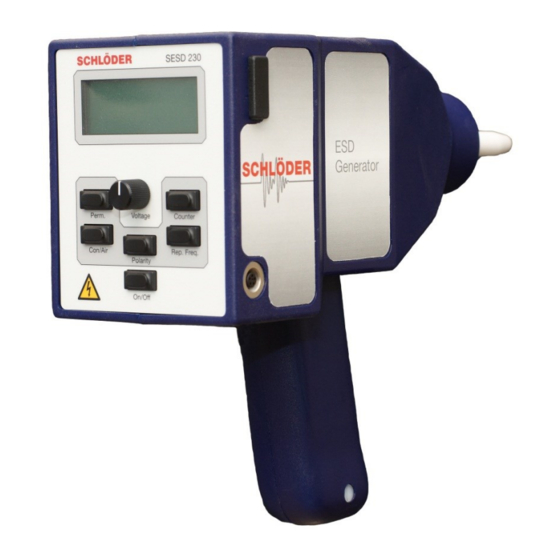
Device functions 4.1 Front panel Normal Mode Setup Mode On / Off ON / OFF switch Polarity of the pulse, Use the adjusted Polarity positive and negative parameters Mode CON / AIR Selection of various → Con/Air Contact discharge or air parameters discharge Selection test level,... -
Page 10: Casing
4.2 Casing 44 13 Figure 2: Housing functions Connector for an optical RS 232 converter [10] Test tip for: a) AIR discharge b) Contact discharge [11] Connector for the discharge return cable [12] Trigger button [13] Connector for the power supply [14] Connector for a tripod Technical drawing... -
Page 11: Function Description
Function description 5.1 ON / OFF - switch After switching on the generator, the LCD display shows the last used parameters. The bottom line shows the charge status of the accumulator (drawing 3). The accumulator should be charged if the bottom line shows two boxes only. -
Page 12: Special Function - Contact Control At Contact Discharge
BUTTON PRESSED! A * appears in the upper left corner of the display. 3. Move the tip of the ESD Generator from a distance of at least 20 cm to the surface of the EUT and move slowly to the EUT until the discharge happens. -
Page 13: Special Function - Displaying Of The Real Discharge Voltage At Air Mode
5.4.2 Special function – displaying of the real discharge voltage at AIR mode In the test mode “AIR” and “Single” the “real discharge voltage” can be shown in the display. After the discharge and hold-on the trigger button [9] the voltage in the display changes from the adjusted voltage to the real discharge voltage. -
Page 14: Polarity Changing During The „Counter-Mode
5.6.2 Polarity changing during the „Counter-Mode“ In the standard mode the ESD pulse discharge positive „+“ or negative „-“. The display shows: + 6,5 kV 140/ 140 By using the counter mode it is possible to change the polarity after half of the nominal discharges happened: 1. -
Page 15: Lcd - Display
5.8 LCD - Display The upper line of the display shows the test voltage in kV and polarity. The second line is empty. In the counter mode – see chapter 5.6 – the display shows the quantity of discharged pulses. The left side of the third line gives information about the test mode (CON / AIR), the right side shows the selected repetition frequency. -
Page 16: Power Supply
5.12 Power supply The generator is connected to the power supply via the socket [13]. The ESD generator can be used either independently, using the built in batteries or while connected to the mains supply. After the charging of the accumulator (the charge line is than showing full on the display), the power supply can be removed and the testing can go on with the accumulator only. -
Page 17: Adjustment Lcd - Display Contrast
5.16 Serial number Each ESD generator has a serial number written into the software. You can display the number on the LCD display as follows: Switch OFF the ESD generator. Press and hold down the buttons [Perm], [Polarity] and [Counter], then press shortly the “ON/OFF”... -
Page 18: Recall - Test Levels 1 - 4 According To Iec/En 61000-4-2
RECALL – Test levels 1 – 4 according to IEC/EN 61000-4-2 6.1 Activation of the function Push button „Perm“ [4], the display shows: Turn the potentiometer [5] to left for activating the test level according to the standard. Successively the test level 4, 3, 2, 1 are displayed. -
Page 19: Setup Functions
(STA), final voltage (END) and step size (STE). In the example shown, there are a total of 46 steps, with five ESD discharges per step. The total test time depends on the selected repetition frequency. -
Page 20: Programming The Automatic Tests
7.3 Programming the automatic tests After activating the setup function - chapter 7.1 - select a memory location that you want to program. In principle, existing memory locations SET 01 - SET 20 can be overwritten or, if not yet occupied, rewritten. All 20 memory locations are numbered, these numbers - SET 01 to SET 20 - cannot be changed. -
Page 21: Storage Oft He Parameters
7.3.2 Storage oft he parameters If all settings have been made as described under 7.3.1, these values can be saved. Using the "Rep. Freq. "[7] all parameters are saved. The display briefly shows the message "Writing Data - READY". If a test is to be carried out immediately with the newly entered values, the data is transferred to the display by means of the "Polarity"... -
Page 22: Self-Test - Function Test
ELECTRODE AND PRESS TRIGGER TO START The release key to the ESD - simulator starts the self-test. During the self-test in the 3rd line of the display the measured value including the permissible range of tolerance is short indicated. After the procedure is terminated, a result list is indicated in the display according to the following pattern:... -
Page 23: Individual Description Of The Steps
Line 2 and 3 of the display indicate the step numbers, whilst line 4 gives the result of each step: means everything is alright, measured value within the tolerance error, measured value too small means error, measured value too high. The example above shows an error while discharging the internal power supply To leave the menu press PERM. -
Page 24: Calibration
GHz. The test setup should correspond to the picture in 8.1. Details of the structure can be found in the standard IEC 61000-4-2 / EN 61000-4-2 - ESD measuring target. The critical parameters such as rise time and pulse width are defined by standards with a tolerance of ± 25% and ±... -
Page 25: Technical Data
11 Technical data SESD Simulator 216 / 230 5 sec adjustable in 100 V steps Output - Holding time via potentiometer (SESD voltage Pre selectable counter 1 - 9999 230) Rotary encoder (SESD Air and contact discharge 216) Shock capacitance 150 pF ±... -
Page 26: Options
Silicon sheet 0,5 mm / 3 mm (IEC/EN 61000 -4-2 / ISO 10605 ) SESD 30 T 1000 Support arm with balancer SESD 8800-4 ESD verification set 2 Ohm (4 GHz) to verify the ESD pulse SESD 30 S120 Remote control software and optical fiber set 13 Schematic block diagram Figure 5 Schlöder GmbH I www.schloeder-emv.de I info@schloeder-emv.de... -
Page 27: Maintenance / Calibration
14 Maintenance / calibration The instrument is largely maintenance-free. We recommend having the instrument calibrated at our premises every two years, e.g. for ISO 9001 certifi- cation. 15 Packing / transport If you return the device to the manufacturer for calibration or repair, use the foam inserts for shipping that you received with the delivery.
Need help?
Do you have a question about the ESD and is the answer not in the manual?
Questions and answers