Table of Contents
Advertisement
Quick Links
Advertisement
Table of Contents

Related Manuals for Tool-Temp TT-13'502 E

Summary of Contents for Tool-Temp TT-13'502 E
- Page 1 Manual B-0821 Heating and Cooling Unit TT-13‘502 E BA 2252e EL-1718d/e/f/i 10/2017 TOOL-TEMP AG Tel.: +41 (0)71 644 77 77 Industriestrasse 30 Fax: +41 (0)71 644 77 00 CH-8583 Sulgen E-Mail: info@tool-temp.ch Schweiz – Suisse – Switzerland Internet: www.tool-temp.ch...
- Page 2 Manual TT-13’502 E - 1 - THE HEATING AND COOLING UNIT HAS TO BE TRANSPORTED IN AN UPRIGHT POSITION AND NEVER ON THE SIDE. SHOULD THE UNIT BE LAID DOWN TO THE SIDE DURING TRANSPORT, IT WILL SUFFER IRREPARABLES DAMAGES.
-
Page 3: Table Of Contents
Temperature controller MP-888 ..................... 18 - 23 12.1 Predefined setups ........................ 19 12.2 Programming MP-888: Heating- and cooling unit TT-13'502 E without flow control ..20 - 23 Spare parts list ........................... 24 - 25 Datasheet time-lag relay ....................... 26 Electrics ............................ -
Page 4: Description
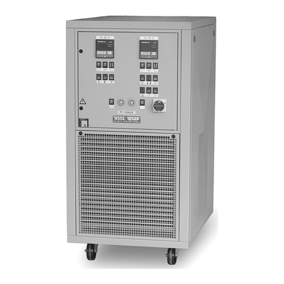
Manual TT-13’502 E - 3 - Description The heating- and cooling unit TT-13’502 E is operating with antipollution and CFC-free refrigerant agent The unit has two independent water circuits with two sealless pumps and two stainless steel water tank of each 25 litres content. -
Page 5: Safety And Use As Agreed
Manual TT-13’502 E - 4 - Safety and use as agreed The heating and cooling unit must not be used for other than the described purpose and within the fixed values for temperature and voltage. Any other use whithout the agreement of the manufacturer is strictly forbidden. -
Page 6: Installation
Manual TT-13’502 E - 5 - Installation Before starting the unit the external connections of the hydraulics and of the electric have to be mounted. CAUTION: STARTING THE UNIT WITHOUT THE PRESCRIBED CONNECTIONS CAN DAMAGE IT. The starting of the unit has to be done in the order of this chapter. After the proper starting the unit is ready to use. -
Page 7: Power Supply
Manual TT-13’502 E - 6 - Power supply Main voltage and frequency according to the serial plate. Pay attention to the local regulations during installation of unit. CAUTION: THE CONNECTION TO THE POWER SUPPLY HAS TO BE DONE BY A QUALIFIED ELECTRICIAN. Colours of cables: phases black / black / black... -
Page 8: Pump Rotation Check
Manual TT-13’502 E - 7 - Pump rotation check As soon as the unit has been connected to the main supply, hoses connections have been made and the water has been filled, the sense of rotation of the pump must be checked. This can be done by shortly switching the unit on. -
Page 9: Safety Devices
Manual TT-13’502 E - 8 - Safety devices The resetting of the thermal relay can be done by pressing the resetting button on the thermal relay of the pump motor contactor. Pump The pump motor is protected by a thermal relay – control lamp Compressor (circuit 1) The compressor is protected by a thermal relay –... -
Page 10: Monitoring Devices
Manual TT-13’502 E - 9 - Monitoring devices Level control The unit is fitted with two level controls yellow lamp on the left is lit: Pre-warning – there is too little water in the tank. The unit is still working and the horn is activated. Water will automatically be refilled (see point 4.4). -
Page 11: Inspections And Maintenance (According To Din 31051)
Manual TT-13’502 E - 10 - Inspection and maintenance (according to DIN 31051) Inspection and maintenance has to be carried out by instructed staff. Please contact the manufacturer or your supplier for eventually necessary steps going beyond. Inspection Before starting the heating and cooling unit the following has to be checked: - condition and tightness of the water connections - electrical connections Maintenance... -
Page 12: Failure Corrective Action
Manual TT-13’502 E - 11 - Failure corrective action symptom possible cause correction Green ON/OFF switch and all - fuse defective - open the front door lamps are not lit, unit does not work - possibly transformer or switch - replace the fuse 5 x 20 mm 1 A defective - replace the defective parts yellow lamp is lit „level control“... - Page 13 Manual TT-13’502 E - 12 - symptom possible cause correction compressor and pump are not internal overload relay of the switch the unit off immediately and working; no fault is indicated compressor (thermostat Pilotherm) get it checked by a refrigeration has responded.
- Page 14 Manual TT-13’502 E - 13 - symptom possible cause correction Lamp „cooling“ is lit no default simply shows that the cooling is active. unit is not cooling anymore but the - loss of refrigerant agent contact the supplier compressor is running - unit is working in the fringe range of the cooling capacity CAUTION:...
-
Page 15: Control Panel Tt-13'502 E
Manual TT-13’502 E - 14 - Control panel TT-13’502 E 1. ON/OFF switch unit see„Temperature 2. ON/OFF switch controller MP-888 / heating programming“ Circuit 2 Circuit 1 3. Level control lamp: pre- warning, not enough liquid in the unit 4. Level control lamp: dropping below the minimum level - Unit switches off... -
Page 16: Views And Dimensions (In Mm)
Manual TT-13‘502 E - 15 - Views and dimensions (in mm) Control panel Main switch Air outlet Air outlet Air inlet 11.1 Front view Circuit 1: Circuit 1: Autom. refill From mould R 3/4“ To mould R 3/4“ R 3/8“ female female thread female thread thread... -
Page 17: Inside View
Manual TT-13‘502 E - 16 - 11.4 Inside view Electrical cabinet autom. refill Expansion valve Pump with motor Pressostat fan (Circuit 2) Condenser Float with microswitch (circuit 2) Fan with motor Tank Pressostat LP/HP (circuit 2) Compressor Plate heat exchanger Pump with motor (Circuit 1) Float with... -
Page 18: Inside View Of Control Panel
Manual TT-13'502 E - 17 - 11.5 Inside view of control panel automatic cut off auxiliary relay temperature controller control fuse (F22, F20) (K25-/2/3/4/5) MP-888 (N1, N2) secondary volt. (F8) transformer (T1) control fuse primary voltage (F7) contactor heating (K3, K4) max. -
Page 19: Temperature Controller Mp-888
Manual TT-13'502 E - 18 - Temperature controller MP-888 cooling switched on heating switched on set point sensor failure actual value controller is triggered from external source with a signal of 0-10 V - or 4-20 mA set point: adjustment of the... -
Page 20: Predefined Setups
Manual TT-13'502 E - 19 - 12.1 Predefined setups Temperature controller circuit 1 (10 – 40°C): The temperature controller must be set on the program P12. Temperature controller circuit 2 (10 – 90°C): The temperature controller must be set on the program P41 and the following parameters has to be changed. - Page 21 12.2 Programming MP-888: Heating- and cooling unit TT-13'502H without flow control U = user - parameter, A = agents - parameter, T = TOOL-TEMP – parameter User code: Press this touch control for 3 seconds to enter into the program steps...
- Page 22 Manual TT-13'502 E - 21 - 12.2 Programming MP-888: Heating- and cooling unit TT-13'502 E without flow control (continuation) Function Factory adjusted (range) U A T Description When using very long sensor lines (Pt 100) the resistor of the line can be compensated.
-
Page 23: Programming Mp-888: Heating- And Cooling Unit Tt-13'502 E Without Flow Control
Manual TT-13'502 E - 22 - 12.1 Programming MP-888: Heating- and cooling unit TT-13'502 E without flow control (continuation) Function Factory adjusted (range) U A T Description Amplification factor P 38 I-proportion (K (1...100%) Controller parameter Modified since version C22 0.0°C / 0.0°F... - Page 24 Manual TT-13'502 E - 23 - 12.1 Programming MP-888: Heating- and cooling unit TT-13'502 E without flow control (continuation) 0: Flow OFF 1: Calibration Flow unit: P 53 Flow unit 2: Litre/Min Value 1 (calibration) should not be set 3: US gallons/Min...
-
Page 25: Spare Parts List
Manual TT-13'502 E - 24 - Spare parts list Standard parts: Bb0300100 Quick fastener for door switch cabinet Bb0300500 Quick fastener for side panel, consisting of: clips, ball head, washer, nut M5 Dc0100400 Castors diam. 100 mm guide roll with 4 mounting holes... - Page 26 Manual TT-13'502 E - 25 - Electrical parts : Digital temperature controller Fa0800326 self-optimized, new MP-888 Pt-100 Digital temperature controller Fa0800328 self -optimized, factory revised MP-888 Pt-100 Fixing clips for controller 2 parts, with straining screw and inside bar Fa0900002...
-
Page 27: Datasheet Time-Lag Relay
Manual TT-13'502 E - 26 - Datasheet timer TOOL-TEMP time-lag relay – TT-13'502 E Designation Time-lag relay Usage elec. wiring Adjusted time diagram Delayed compressor K23/2 30 sec.
Need help?
Do you have a question about the TT-13'502 E and is the answer not in the manual?
Questions and answers