Table of Contents
Advertisement
Quick Links
Advertisement
Table of Contents
Troubleshooting

Related Manuals for NI USRP-2920


Summary of Contents for NI USRP-2920
- Page 1 USRP-2920/2921/2022 Getting Started 2022-07-11...
-
Page 2: Table Of Contents
USRP-2920 Front Panel and LEDs........ -
Page 3: Usrp Device Getting Started Guide
■ USRP-2922 Software Defined Radio Device ■ The USRP-2920/2921/2922 device can send and receive signals for use in various communications applications. This device ships with the NI-USRP instrument driver, which you can use to program the device. Verifying the System Requirements To use the NI-USRP instrument driver, your system must meet certain requirements. -
Page 4: Verifying The Kit Contents
USRP-2920/2921/2022 Getting Started Note Do not install a device if it appears damaged in any way. 3. Unpack any other items and documentation from the kit. Store the device in the antistatic package when the device is not in use. -
Page 5: Environmental Guidelines
LabVIEW Communications System Design Suite LabVIEW MathScript RT Module, available for download at ni.com/ ■ downloads USRP MIMO sync and data cable, available at ni.com, to synchronize clock ■ sources Additional SMA (m)-to-SMA (m) cables to connect both channels with ■... -
Page 6: Installing The Software
2. Follow the instructions below that correspond with the ADE that you installed. Installing the Software Using NI Package Manager Ensure that you have installed the latest version of NI Package Manager. To access the download page for NI Package Manager, go to ni.com/info... -
Page 7: Installing The Device
2. Attach the antenna or cable to the front panel terminals of the USRP device as desired. 3. Use the Ethernet cable to connect the USRP device to the computer. For maximum throughput over Ethernet, NI recommends that you connect each USRP device to its own dedicated gigabit Ethernet interface on the host computer. -
Page 8: Synchronizing Multiple Devices (Optional)
RX 1 TX 1 port of the transmitter, and attach another antenna to the RX 2 port of the receiver. The NI-USRP driver ships with some examples that you can use to explore the MIMO connection, including USRP EX Rx Multiple Synchronized Inputs (MIMO Expansion) and USRP EX Tx Multiple Synchronized Outputs (MIMO Expansion). - Page 9 1. Verify that your device is powered on and connected to your computer using the gigabit Ethernet interface. 2. Select Start » All Programs » National Instruments » NI-USRP » NI-USRP Configuration Utility to open the NI-USRP Configuration Utility, as shown in the following figure.
- Page 10 USRP-2920/2921/2022 Getting Started Your device should appear in the list on the left side of the tab. 3. Select the Devices tab of the utility. 4. In the list, select the device for which you want to change the IP address.
- Page 11 USRP-2920/2921/2022 Getting Started Confirming Network Connection 1. Select Start » All Programs » National Instruments » NI-USRP » NI-USRP Configuration Utility to open the NI-USRP Configuration Utility. 2. Select the Devices tab of the utility. Your device should appear in the Device ID column.
-
Page 12: Programming The Device
Device IP Address USRP Device 0 192.168.10.1 255.255.255.0 192.168.10.2 USRP Device 1 192.168.10.1 255.255.255.0 192.168.10.3 Table 4. Single Host Ethernet Interface—Unmanaged Switch Configuration Programming the Device You can use the NI-USRP instrument driver to create communications applications for the USRP device. ni.com... -
Page 13: Ni-Usrp Examples
Use USRP Rx Continuous Async to confirm that the device receives signals and is connected correctly to the host computer. 1. Navigate to Learning » Examples » Hardware Input and Output » NI-USRP » NI- USRP. 2. Select Rx Continuous Async. Click Create. -
Page 14: Troubleshooting
Why Doesn't the Device Power On? Check the power supply by substituting a different adapter. Why Does USRP2 Appear Instead of the USRP Device in the NI-USRP Configuration Utility? An incorrect IP address on the computer may cause this error. Check the IP ■... - Page 15 You may need to update the device for compatibility with the latest version of the software. When you use the NI-USRP API, a default FPGA loads from persistent storage on the device. The driver software media also includes the NI-USRP Configuration Utility, which you can use to update the devices.
- Page 16 Why Doesn't the USRP Device Appear in MAX? MAX does not support the USRP device. Use the NI-USRP Configuration Utility instead. Open the NI-USRP Configuration Utility from the Start menu at Start » All Programs » National Instruments » NI-USRP » NI-USRP Configuration Utility.
-
Page 17: Network Troubleshooting
■ Why Doesn't the NI-USRP Configuration Utility Return a Listing for My Device? If the NI-USRP Configuration Utility does not return a listing for your device, search for a specific IP address. 1. Navigate to <Program Files>\National Instruments\NI-USRP\. 2. <Shift>-right-click the utilities folder, and select Open command window here from the shortcut menu to open a Windows command prompt. - Page 18 4. Continue to press the safe-mode button until the front panel LEDs blink and remain solid. 5. While in safe-mode, run the NI-USRP Configuration Utility to change the IP address from the default, 192.168.10.2, to a new value. 6. Power cycle the device without holding the safe-mode button to return the normal mode.
-
Page 19: Front Panels And Connectors
USRP-2920/2921/2022 Getting Started Note If the device IP address is on a different subnet from the host network adapter, the host system and configuration utility cannot communicate with and configure the device. For example, the utility recognizes, but cannot configure a device with an IP address of 192.168.11.2 connected to a host network adapter with a static IP... -
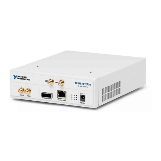
Page 20: Usrp-2920 Front Panel And Leds
USRP device TX 1 RX 1 or RX 2 connector, ensure that the device cannot generate signal transients greater than the RF and DC specifications of the USRP device TX 1 RX 1 or RX 2 connector. USRP-2920 Front Panel and LEDs NI USRP - 2920 RX 1... -
Page 21: Usrp-2921 Front Panel And Leds
USRP-2920/2921/2022 Getting Started LED Description Color Indication Indicates the transmit status of the device. Off The device is not transmitting data. Green The device is transmitting data. Indicates the status of the physical MIMO The devices are not connected using cable link. - Page 22 USRP-2920/2921/2022 Getting Started Connector Description REF IN Input terminal for an external reference signal for the local oscillator (LO) on the device. REF IN is an SMA (f) connector with an impedance of 50 Ω and is a single- ended reference input. REF IN accepts a 10 MHz signal with a minimum input power of 0 dBm(.632 Vpk-pk) and a maximum input power of...
-
Page 23: Usrp-2922 Front Panel And Leds
USRP-2920/2921/2022 Getting Started USRP-2922 Front Panel and LEDs NI USRP - 2922 RX 1 RX 2 TX 1 400 MHz - 4.4 GHz 6 V 3 A REF IN PPS IN MIMO EXPANSION GB ETHERNET POWER Connector Description RX 1 Input and output terminal for the RF signal. -
Page 24: Where To Go Next
NI-USRP Instrument Driver USRP Device LabVIEW Help Specifications NI-USRP Sample Projects* NI-USRP Help* NI-USRP Help* DISCOVER more about your products through ni.com. RF Solutions Services Upd ates ni.com/rf ni.com/services ni.com/updates *This item is also installed with the driver software. ni.com... -
Page 25: Ni Services
NI product. Product registration facilitates technical support and ensures that you receive important information updates from NI corporate headquarters is located at 11500 N Mopac Expwy, Austin, TX, 78759-3504, USA. © National Instruments © 2022 National Instruments Corporation.
Need help?
Do you have a question about the USRP-2920 and is the answer not in the manual?
Questions and answers