BIRD Termaline 8890 Series Operation Manual
Load resistor
Hide thumbs
Also See for Termaline 8890 Series:
- Operation manual (32 pages) ,
- Instruction book (36 pages)
Table of Contents
Advertisement
Quick Links
®
Termaline
Load Resistor
Series 8890
Operation Manual
This unit requires the supplied vent plug be installed prior to use.
Operating the unit without the vent plug installed WILL result in equipment damage and may
cause personal injury.
© Copyright 2023 by Bird Technologies, Inc.
Instruction Book Part Number 920-8890S Rev. E
®
®
Termaline
and Tenuline
are Registered Trademarks
of Bird Electronic Corporation
Advertisement
Table of Contents

Related Manuals for BIRD Termaline 8890 Series


Summary of Contents for BIRD Termaline 8890 Series
- Page 1 This unit requires the supplied vent plug be installed prior to use. Operating the unit without the vent plug installed WILL result in equipment damage and may cause personal injury. © Copyright 2023 by Bird Technologies, Inc. Instruction Book Part Number 920-8890S Rev. E ®...
- Page 3 Safety Precautions Safety Precautions The following are general safety precautions that are not necessarily related to any specific part or procedure, and do not necessarily appear elsewhere in this publication. These precautions must be thoroughly understood and apply to all phases of operation and maintenance. Keep Away From Live Circuits Operating Personnel must at all times observe general safety precautions.
-
Page 4: Safety Symbols
Termaline® Load Resistor Safety Symbols Warnings call attention to a procedure, which if not correctly performed, could result in personal injury. Cautions call attention to a procedure, which if not correctly performed, could result in damage to the instrument. Calls attention to supplemental information. This symbol indicates that a shock hazard exists if the precautions in the instruction manual are not followed. -
Page 5: Warning Statements
Safety Precautions Warning Statements The following safety warnings appear in the text where there is danger to operating and maintenance personnel, and are repeated here for emphasis. The vent plug must be installed at all times when the unit is in operation or cooling. Always check to ensure vent plug is installed prior to operation. -
Page 6: Caution Statements
Maximum power is 1,250 W when the blower is not running. If the indicator light should turn off, immediately reduce RF power to less than 1,250 W. On page 12. Use only Bird coolant, P/N 5-1070, to prevent damage to the load. On page 16. -
Page 7: Safety Statements
Safety Precautions Safety Statements USAGE ANY USE OF THIS INSTRUMENT IN A MANNER NOT SPECIFIED BY THE MANUFACTURER MAY IMPAIR THE INSTRUMENT’S SAFETY PROTECTION. EL USO DE ESTE INSTRUMENTO DE MANERA NO ESPECIFICADA POR EL FABRICANTE, PUEDE ANULAR LA PROTECCIÓN DE SEGURIDAD DEL INSTRUMENTO. BENUTZUNG WIRD DAS GERÄT AUF ANDERE WEISE VERWENDET ALS VOM HERSTELLER BESCHRIEBEN, KANN DIE GERÄTESICHERHEIT BEEINTRÄCHTIGT WERDEN. - Page 8 Termaline® Load Resistor SERVICE SERVICING INSTRUCTIONS ARE FOR USE BY SERVICE - TRAINED PERSONNEL ONLY. TO AVOID DANGEROUS ELECTRIC SHOCK, DO NOT PERFORM ANY SERVICING UNLESS QUALIFIED TO DO SERVICIO LAS INSTRUCCIONES DE SERVICIO SON PARA USO EXCLUSIVO DEL PERSONAL DE SERVICIO CAPACITADO.
- Page 9 Safety Precautions CONNECT INTERLOCK TO TRANSMITTER BEFORE OPERATING. BRANCHER LE VERROUILLAGE À L'ÉMETTEUR AVANT EMPLOI. CONECTE EL INTERBLOQUEO AL TRANSMISOR ANTES DE LA OPERACION. VOR INBETRIEBNAHME VERRIEGELUNG AM SENDER ANSCHLIESSEN. PRIMA DI METTERE IN FUNZIONE L'APPARECCHIO, COLLEGARE IL DISPOSITIVO DI BLOCCO AL TRASMETTITORE.
-
Page 10: About This Manual
When inquiring about updates to this manual refer to the part number and revision on the title page. Chapter Layout Introduction — Describes the features of the Bird Termaline, Semiconductor, RF Load Resistor lists equipment supplied and optional equipment, and provides power-up instructions. Theory of Operation —... -
Page 11: Table Of Contents
Table of Contents Safety Precautions ..............i Safety Symbols . - Page 12 Termaline® Load Resistor Chapter 6 Maintenance ............. 13 Troubleshooting .
-
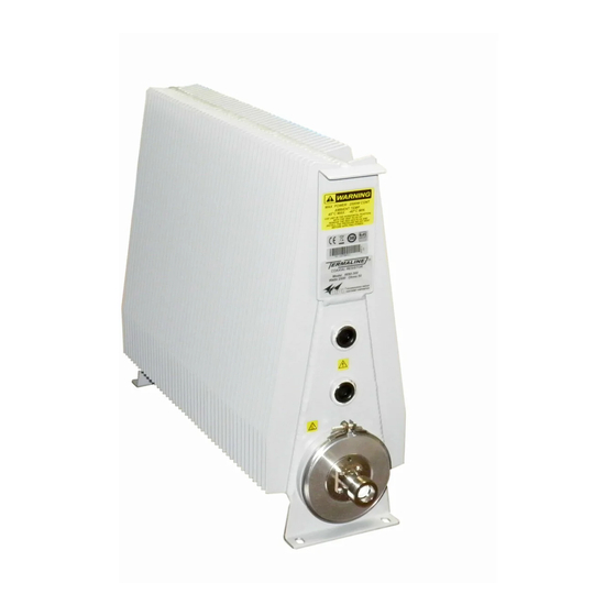
Page 13: Chapter 1 Introduction
Introduction The Bird 8890 series loads are portable, 50 ohm, coaxial RF transmission line terminations, designed for frequency ranges of DC – 2.4 GHz. The 8890 series D loads are designed for use in the UHF (470 – 860 MHz) band, otherwise they are identical to the standard series. - Page 14 Termaline® Load Resistor Figure 1 Bird 889x Series Outline Drawing - No Blower Figure 2 Bird 889x Series Outline Drawing With Blower...
-
Page 15: Chapter 2 Theory Of Operation
Theory of Operation Load Resistor Bird 8890 series loads consist of a thin-film-on-ceramic resistor immersed in a dielectric coolant. The resistor, individually selected for its accuracy, is enclosed in a special housing. When surrounded by the coolant, this produces a uniform, practically reflectionless line termination over the specified frequencies. -
Page 16: Chapter 3 Installation
If the shipping container is not damaged, unpack the unit. Save shipping materials for repackaging. 2. Inspect unit for visual signs of damage. If there is damage, immediately notify the shipping carrier and Bird Technologies. Site and Shelter Requirements The unit should be operated in a dry, dust and vibration free environment. -
Page 17: Mounting The Load
Operation in any other orientation will cause insufficient cooling of the unit leading to premature failure. Bird 8890 series Loads are equipped for either portable use or fixed installation. The mounting brackets on the front and rear faces have four mounting slots arranged in a 4 ... -
Page 18: Thermoswitch
Connector - P/N 2450-018 Installing the Thermoswitch Bird 8890 series Load thermoswitch is normally closed, opening at 155 °C (311 °F), with a rating of 10A at 120VAC and 5A at 230VAC. A control thermoswitch, P/N 2450-085, is used to control the optional blower assembly. It is normally open, closing at 155 °C (311 °F), with a rating of 10A @ 120VAC and 5A @ 230VAC. -
Page 19: Installing The Interlock Connection
Installation The vent plug must be used at all times when the unit is in operation or cooling. Always check to ensure vent plug is installed prior to operation. Failure to do so WILL result in damage to the equipment and endanger the operator’s safety. 11. -
Page 20: Connecting Rf Power
Termaline® Load Resistor Connecting RF Power Before first using the load, perform the following steps. 1. Wipe all connectors and insulator surfaces on the transmission line face with a clean soft cloth. 2. Check the RF input connector for signs of wear, damage, or dirt. 3. -
Page 21: Using A Unflanged Coupling
Installation Using a Unflanged Coupling 1. Insert the center bullet, see Figure 5 2. Push until it sets the midpoint nibs. 3. Position the outer sleeve, with clamping bands, over the input connector. 4. Set the transmission line snugly against the coupling stops. 5. -
Page 22: Chapter 4 Operating Instructions, No Blower
If installed, connect optional interlock before applying RF power. Normal Operation Bird 8890 series– 300 loads have no indicators or operating controls. They require no special operating procedures or surveillance when their performance limits are not exceeded. Follow the instructions for the specific transmitter equipment. -
Page 23: Chapter 5 Operating Instructions, With Blower
If installed, connect optional interlock before applying RF power. Blower Controls Bird 8890 series –315 and –320 Loads are equipped with a control switch and indicator light on the front of the blower assembly. The switch is labeled MANUAL/AUTOMATIC. ... -
Page 24: Operating Under Abnormal Conditions
Termaline® Load Resistor Operating Under Abnormal Conditions The load can be subjected to higher power levels for short intervals. If this is likely, make sure the interlock is properly connected to prevent damage to the load. A properly connected interlock will prevent overload. Maximum power is 1,250 W when the blower is not running. -
Page 25: Chapter 6 Maintenance
Chapter 6 Maintenance This chapter covers cleaning, inspection, trouble-shooting, and specifications for the Bird 8890 series Loads. Never attempt to connect or disconnect RF equipment from the transmission line while RF power is being applied. Leaking RF energy is a potential health hazard. -
Page 26: Routine Maintenance
Termaline® Load Resistor Routine Maintenance shows the location of components which may be referred to in this section. Figure 6 Figure 6 Maintenance and Repair Locations, Without Blower Figure 7 Maintenance and Repair Locations, With Blower Clean the Load The outside surface of the instrument should be wiped free of dust and dirt when necessary. -
Page 27: Clean The Blower Assembly
Maintenance Clean the Blower Assembly The intake grills, fans, and inside of the baffles should be wiped free of dust and dirt when necessary. Excessive dust will interfere with heat dissipation. When the blower assembly is installed, it will be necessary to partially disassemble the blower to clean the load’s radiator fins. -
Page 28: Inspect The Coolant
1. Remove the load resistor (See "Replacing the Load Resistor" on page 19 Use only Bird coolant, P/N 5-1070, to prevent damage to the load. The coolant should be clear, with a faint yellow tinge, and have a slightly sweet smell. -
Page 29: Dc Resistance Measurement
Maintenance DC Resistance Measurement Never attempt to connect or disconnect RF equipment from the transmission line while RF power is being applied. Leaking RF energy is a potential health hazard. It is recommended that this resistance check be performed each time the load is to be used. 1. -
Page 30: Repair
Replacing the RF Connector ONLY the Model 8890 has a special Bird “QC” connector which allows easy changing of the RF connector. This does not disturb the coolant seal or affect the electrical continuity of the load. To change the connector, proceed as follows: 1. -
Page 31: Replacing The Indicator Light
Maintenance Replacing the Indicator Light 1. Remove the four 8-32 pan head screws from the front and back of the base frame. 2. Pull the fan guard straight off the bottom. 3. Remove the quick disconnects on the light. 4. Unscrew the retaining sleeve. 5. -
Page 32: Replacing The Fan
Termaline® Load Resistor 16. Verify the O-Ring is installed on the vent plug. 17. Install the vent plug. Replacing the Fan Disconnect the unit from all power sources before servicing. The unit may be energized from multiple sources. The potential for electric shock exists. 1. -
Page 33: Storage And Shipment
Any maintenance or service procedure beyond the scope of those in this chapter should be referred to a qualified service center. If the unit needs to be returned for any reason, request an Return Material Authorization (RMA) through the Bird Technologies website. All instruments returned must be shipped prepaid and to the attention of the RMA number. -
Page 34: Specifications
Termaline® Load Resistor Specifications Frequency Range 8891D300, 8892D300, 8892D13-30, 8892D320 470 – 860 MHz All other models DC – 2.4 GHz Power Rating Peak Power for Pulse Width 2500 W continuous duty 1 µs 150 kW 10 µs 115 kW 100 µs 80 kW 1000 µs... -
Page 35: Replacement Parts
Maintenance Finish Grey Powder Coat 1 Power rating with blower installed and operating: 5000 W Power rating with blower installed and NOT operating: 1250 W 2 Set the duty factor so that the average power rating of the load is not exceeded. 3 For models 8890-300, -315, and -320 VSWR Measured using a female N connector 4 Derate RF power by 2.5% for every 305m (1,000 ft.) above 1,520m (5,000 ft.). -
Page 36: Available "Qc" Type Connectors
Termaline® Load Resistor Available “QC” Type Connectors Connector Part Number BNC-Female 4240-125 BNC-Male 4240-132 C-Female 4240-100 C-Male 4240-110 HN-Female 4240-268 HN-Male 4240-278 LC-Female 4240-031 LC-Male 4240-025 Open Term.# 10-32 Nut 4240-080 LT-Female 4240-018 LT-Male 4240-012 N-Female 4240-062 N-Male 4240-063 SC-Female 4240-090 SMA-Female 4240-336... -
Page 37: Limited Warranty
Limited Warranty All products manufactured by Seller are warranted to be free from defects in material and workmanship for a period of one (1) year, unless otherwise specified, from date of shipment and to conform to applicable specifications, drawings, blueprints and/or samples. Seller’s sole obligation under these warranties shall be to issue credit, repair or replace any item or part thereof which is proved to be other than as warranted;...
Need help?
Do you have a question about the Termaline 8890 Series and is the answer not in the manual?
Questions and answers