
Subscribe to Our Youtube Channel
Related Manuals for GEM FLOW COUPLER


Summary of Contents for GEM FLOW COUPLER
- Page 1 Global Excellence in Microsurgery FLOW COUPLER Monitor Global Excellence in Microsurgery Channel B...
- Page 2 This page intentionally left blank...
- Page 3 Symbols referenced on labeling Symbol Glossary per US FD&C Act: Additional symbols and graphics on the product labeling that are Standard Symbol Symbol Title Symbol Meaning Symbol No. not required by the US FD&C Act: ISO 15223-1* Manufacturer Manufacturer 5.1.1 Symbol Symbol Description ISO 15223-1...
- Page 4 • If procedures are not followed, possible equipment or software damage may occur. probe that is press- t onto one of the rings. When the FLOW COUPLER Device is used in conjunction with the FLOW COUPLER Monitor, the FLOW COUPLER System is intended to •...
-
Page 5: Product Specifications
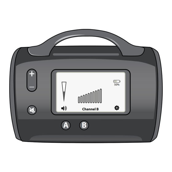
Component Interfaces (See Figure 1): (12) Power Supply connector: Connect Power Supply to the Monitor. (13) External lead connector: Connect external lead(s) to the Monitor. Up to 2 external leads can be connected to the Monitor. Figure 1: FLOW COUPLER Monitor Description... - Page 6 Settings: Touch the settings mode icon Settings on the screen to display and/or change System Display additional settings for: Volume settings During the battery charge, Display settings, System information and Volume Language a charging status icon is Language section. displayed. Channel B Selecting Volume button in Wi-Fi Selection...
-
Page 7: Operation
Need charging software, and the date and time. Operation: Transmission Frequency: 20 MHz Transmission Characteristic: Pulsed transmission, continuous reception Sensitivity: See FLOW COUPLER Device and System IFU Environment: Recommended shipping and storage temperature: 5 C to 40, non-condensing. Avoid direct sunlight... - Page 8 Place the Monitor on a suitable stand, cart or table outside the sterile eld, near the Ensure that correct Channel Selection Button is illuminated, and Channel Selection physician who will be using the FLOW COUPLER System, and within 4 feet of the patient. Indicator on the LCD screen is displayed.
- Page 9 Instructions for Use (Postoperative Bedside Monitoring): Disconnect the Power Supply from the electrical outlet. Transport the patient with the Monitor and the Power Supply to postoperative care area: use the handle on the Monitor to prevent damages and for safe handling of the Monitor. Repeat steps 3 to 7 outlined in Intraoperative Monitoring Instructions for use.
-
Page 10: Special Instructions
3. Do not put liquid near the speaker. 4. The FLOW COUPLER Monitor is no longer usable when hardware buttons, LCD screens are Depth for TIS inoperable, or audible signal is not generated when connected to the FLOW COUPLER probe. - Page 11 Acoustic output format for track 1: Non-Autoscanning Mode System: FLOW COUPLER Monitor and Probe System Operating Mode: PW Doppler Transducer Model: 20 MHz Doppler Probe Application(s): Other (intra-operative and post-operative) Index Label Below Below Surface Surface Surface Surface 0.0105 9.80E-4 Maximum index value 5.14E-3...
-
Page 12: Performance Criteria
RF Emissions, CISPR 11:2015 +A1:2016 Group 1 The FLOW COUPLER Monitor system uses RF energy only for its internal function. Therefore, its RF emissions are very low and are not likely to cause any interference in nearby electronic equipment. RF Emissions, CISPR 11:2015 +A1:2016... - Page 13 Mains power quality should be that of a typical commercial or hospital envi- Bursts Immunity ronment. The FLOW COUPLER Monitor may go into the charging state due to transient disturbance. It will require manual reset of the Monitor by pressing IEC 61000-4-4:2012 power ON button.
- Page 14 IEC 61000-4-11:2004 / AMD1:2017 0% (100% reduction), 1 cycle 0% (100% reduction), 1 cycle environment. If the user of the FLOW COUPLER Monitor requires continued 70% (30% reduction) UT, 0.5 sec 70% (30% reduction) UT, 0.5 sec operation during power mains interruptions, it is recommended that the...
- Page 15 Probe Connector to External Lead • External Lead to Monitor Monitor not functioning Connect a di erent FLOW COUPLER Monitor. Contact Synovis Micro Companies Alliance Customer Service (Ph. +1 205.941.0111 or +1 800.510.3318 (U.S. only). Weak sound output Volume is too low Increase volume by pressing Volume Increase Button or touch-and-drag Volume Indicator on the LCD screen.
-
Page 16: Accessories And Parts
LIMITED WARRANTY The FLOW COUPLER Monitor is warrantied for one year from the date of shipment from Synovis MCA against defects in materials and workmanship. Defective GEM FLOW COUPLER Monitors will be repaired or replaced, at Synovis MCA’s option, when returned prepaid to Synovis MCA within this year. The customer assumes full responsibility that this equipment meets the speci cations, capabilities and other requirements of the customer. - Page 17 This page intentionally left blank...
- Page 18 This page intentionally left blank...
- Page 19 This page intentionally left blank Global Excellence in Microsurgery...
- Page 20 Synovis Micro Companies Alliance, Inc. (a subsidiary of Baxter International Inc.), 439 Industrial Lane, Birmingham, AL 35211-4464 USA. (Tel) 205.941.0111 (Toll free) 800.510.3318 (Fax) 205.941.1522 www.synovismicro.com MS-14093, Rev H Flow Coupler and the GEM design are trademarks of Baxter International Inc., or its subsidiaries. 2022-10-30...
Need help?
Do you have a question about the FLOW COUPLER and is the answer not in the manual?
Questions and answers