
Subscribe to Our Youtube Channel
Related Manuals for GEM FLOW COUPLER


Summary of Contents for GEM FLOW COUPLER
- Page 1 Global Excellence in Microsurgery Global Excellence in Microsurgery FLOW COUPLER Monitor Global Excellence in Microsurgery 10:15 Channel B...
- Page 2 Symbols referenced on labeling Symbol Glossary per US FD&C Act: Additional symbols and graphics on the product labeling that are Standard Symbol Symbol Title Symbol Meaning Symbol No. not required by the US FD&C Act: ISO 15223-1* Manufacturer Manufacturer 5.1.1 Symbol Symbol Description ISO 15223-1...
- Page 3 Doppler probe that is press-fit onto one of the rings. When the FLOW COUPLER Device is used in • During the use of all ultrasound devices, the operator should minimize the exposure of...
-
Page 4: Product Specifications
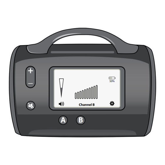
• Volume Decrease Button (3): A button that will decrease the volume of the audible Doppler signal. • Mute Button (4): A button that mutes the sound. • Channel Selection Buttons (5): A button that sets the Doppler to a channel. Figure 1: FLOW COUPLER Monitor Description The selected channel button will be illuminated. - Page 5 LCD Controls (See Figure 1): When the battery level is Volume Indicator (6): A graduated scale in the LCD screen indicates the volume of the below 10%, critically low audible Doppler signal. Volume can be changed by touch-and-drag the scale on the battery screen appears and touchscreen.
-
Page 6: Audio Settings
MAC Addr: 0080E1FFF501 IP Addr: 192.168.1.3 Date/Time 2018/04/28 13:00:17 WiFi Settings Screen lets you Device Info Screen contains choose your own specific Device Info Wi-Fi Selection technical specifications including WiFi settings to connect versions of the hardware and K70 Ver: 2.2.0.7 Device Info the device to your wireless... -
Page 7: Operation
Power Supply to the monitor as instructed in Step 3, if desired. Class II External Power Supply shipped with the monitor or sold separately (GEM1020PS-2), Refer to FLOW COUPLER Device and System Instructions for Use for handling of the A/C to D/C Power Supply Internally rechargeable Lithium Ion Battery, Power Requirements: FLOW COUPLER Device. -
Page 8: Special Instructions
Do not pour or spray liquid directly on the Monitor. Allow to air dry before use. 3. Do not put liquid near the speaker. Cranial Bone Thermal Index The Following Sections apply to the FLOW COUPLER 20 MHz Doppler Probe Attenuated Peak-Rarefractional Acoustic Pressure Acoustic Output: Power Output There are no user controls meant to affect acoustic outputs. - Page 9 Acoustic output format for track 1: Non-Autoscanning Mode System: 20 MHz FLOW COUPLER Monitor and Probe System Operating Mode: PW Doppler Transducer Model: 20 MHz Doppler Probe Application(s): Other (intra-operative and post-operative) Index Label Below Below Surface Surface Surface Surface 0.0105...
-
Page 10: Performance Criteria
Guidance and manufacturer’s declaration – electromagnetic emissions The 20 MHz FLOW COUPLER Monitor system is intended for use in the electromagnetic environment specified below. The user of the 20 MHz FLOW COUPLER Monitor should assure that it is used in such an environment. - Page 11 Guidance and manufacturer’s declaration – electromagnetic immunity The 20 MHz FLOW COUPLER Monitor system is intended for use in the electromagnetic environment specified below. The user of the 20 MHz FLOW COUPLER Monitor should assure that it is used in such an environment.
- Page 12 Mains power quality should be that of a typical commercial or (Voltage dips: 0% U ; 0.5 cycle, 0% U hospital environment. If the user of the 20 MHz FLOW COUPLER 0% U ; 0.5 cycle at 0°, 45°, 90°, 135°, 180°, cycle, and 0% U ;...
- Page 13 Recommended separation distances between portable/mobile RF communications equipment and the 20 MHz FLOW COUPLER Monitor system. The 20 MHz FLOW COUPLER Monitor is intended for use in an electromagnetic environment in which radiated RF disturbances are controlled. The customer or the user of the FLOW COUPLER Monitor can help prevent electromagnetic interference by maintaining a minimum distance between portable and mobile RF communications equipment (transmitters) and the Doppler system as recommended below, according to the maximum output power of the communications equipment.
-
Page 14: Troubleshooting Guide
Troubleshooting: There are no user serviceable components inside this device. Disassembly of the internal components of this unit may result in circuit damage. Troubleshooting Guide Standard Possible Problem Solution No sound No power Verify Monitor power is on output No power Check all connections: •... -
Page 15: Storage Conditions
LIMITED WARRANTY The FLOW COUPLER Monitor is warrantied for one year from the date of shipment from Synovis MCA against defects in materials and workmanship. Defective GEM FLOW COUPLER Monitors will be repaired or replaced, at Synovis MCA’s option, when returned prepaid to Synovis MCA within this year. The customer assumes full responsibility that this equipment meets the specifications, capabilities and other requirements of the customer. - Page 16 Synovis Micro Companies Alliance, Inc. (a subsidiary of Baxter International Inc.), 439 Industrial Lane, Birmingham, AL 35211-4464 USA. (Tel) 205.941.0111 (Toll free) 800.510.3318 (Fax) 205.941.1522 www.synovismicro.com Flow Coupler and the GEM design are trademarks of Baxter International Inc., or its subsidiaries. MS-14093, Rev A...
Need help?
Do you have a question about the FLOW COUPLER and is the answer not in the manual?
Questions and answers