Advertisement
Quick Links
Advertisement

Subscribe to Our Youtube Channel
Related Manuals for Fluke DATAPAQ SolarPaq

Summary of Contents for Fluke DATAPAQ SolarPaq
- Page 1 SolarPaq USER MANUAL for use with Issue 1 MA5050A...
- Page 3 SolarPaq User Manual for use with Issue 1 Datapaq is the world’s leading manufacturer ® of process temperature-monitoring instrumentation. The company maintains this leadership by continual development of its advanced, easy-to-use systems. Europe & Asia North & South America Datapaq Ltd. Datapaq, Inc.
-
Page 4: Safety Warnings
SAFETY WARNINGS For safe use of Datapaq equipment, always: • Take care to follow its supplied instructions. • Observe any warning signs shown on the equipment itself. Indicates potential hazard. On Datapaq equipment this normally warns of high temperature, but where you see the symbol you should consult the manual for further explanation. - Page 5 CO N T EN T S Introduction Basic Hardware and Its Use System Components Thermal Barriers 10 Thermocouple Probes 17 Running a Temperature Profile 17 Overview 18 Preparing the Logger 18 Installing the Logger in the Thermal Barrier 19 Placing the System in the Furnace 19 Removing from the Furnace and Downloading Data 20 Preparing the Data for Analysis 21 Using Hardwired Telemetry...
- Page 7 Introduction Datapaq SolarPaq, incorporating Insight Solar Tracker software, is a ® ® ™ complete system for monitoring and analyzing the temperature profiles of products within a wide range of heat-treatment processes used in the manufacture of photovoltaic cells. Power and flexibility make SolarPaq a perfect tool for process-temperature monitoring, from commissioning and troubleshooting to process optimization, ensuring consistent quality of product and maximum efficiency.
- Page 8 For full details on use of the Insight software, refer to the online Help system available after the software is installed. Introduction SOLARPAQ...
-
Page 9: System Components
Basic Hardware and Its Use To accommodate the range of different processes which are involved in the manufacture of photovoltaic cells, SolarPaq systems are supplied in a variety of configurations, depending on the intended application. The information in this chapter applies to all systems. Some processes in cell manufacture require special additional considerations, and these are dealt with separately: •... - Page 10 When used in vacuum processes, and when the barrier has been left standing for some time, the vacuum may take longer than normal to pump out due to out- gassing from the ceramic insulation. Selecting a Thermal Barrier Before running a temperature profile of a given process, the user must ensure that the SolarPaq system is suitable.
- Page 11 Thermocouple Specifications The standard thermocouple probe for furnace operation in photovoltaic-cell manufacture is type K, which has a hot junction combining nickel-chromium alloy and nickel-aluminum alloy. International specifications for type K define a sensitivity and linearity over the range 0–1,250°C, though operating range is limited in practice by the cable insulation (see below).
- Page 12 At Temperatures Greater Than Product 400°C See note* 430°C Tetrafluoroethylene 440°C Hexafluoropropylene 475°C Perfluoroisobutylene 500°C Carbonyl fluoride*, which, in moist air, converts to the acid gas hydrogen fluoride * May also be produced if PTFE tape is kept at 400°C for an extended time. Health-hazard Data •...
- Page 13 Binder-less Glass-fiber Thermocouple 1/0.2 flat-pair cable, hot junction flattened for improved thermal contact. Complies with ANSI MC96.1 Special Limits of Error. Maximum 1,000°C. PA1144 0.5 m/1.6 ft PA1145 1.0 m/3.3 ft Kapton Tape – High-temperature Adhesive For securing exposed-junction thermocouples. Pressure-sensitive silicone adhesive. Maximum 400°C.
- Page 14 Probe Attachment Attaching probes to the product is a key step in obtaining accurate and repeatable temperature profiles. There are a number of options, depending on the exact nature of the product and the temperatures at which it is processed: •...
- Page 15 ○ If the reading does not change, the thermocouple is short circuit and must be replaced. ○ If the probe measures air temperature, the cable may have damage which has created a new hot junction. ○ If the thermometer shows a decrease, the thermocouple connections are reversed.
- Page 16 Basic Hardware SOLARPAQ...
-
Page 17: Running A Temperature Profile
Running a Temperature Profile The information in this chapter applies to all SolarPaq systems, and should be read in conjunction with detailed guidance on use of the specific system: • Anti-reflective coating (sputtering) processes (p. 23). • Contact firing (metallization) (p. 27). •... - Page 18 • If necessary, set the furnace start position within the data. • Add any additional information that you wish to have recorded with the profile data. After this, Insight can be used to analyze the profile data as required. Preparing the Logger If the data logger is being connected to a PC for the first time, it is necessary to enable communication between them.
- Page 19 3. If the trigger mode is Start Button, press and hold the start button for about 1 second until the green LED starts to flash. 4. Close the thermal barrier, ensuring that the lid is securely fastened. Placing the System in the Furnace Line speed through the furnace may be very high, so care must be taken to prepare everything before loading any part of the system into the process.
- Page 20 simultaneously. A red logger-status LED flashing every 5 seconds indicates data stored in the logger but not yet downloaded to the PC. Download the data from the logger to the PC using the Insight software. For the procedures involved, see your dedicated logger manual or the Insight Help system (on Insight’s menu bar, select Help >...
-
Page 21: Troubleshooting
correction factors in a ‘correction factor file’, and correction is achieved simply by applying this file to the data. For details of the creation and use of correction factor files, see the topic ‘Correction Factors’ in Insight’s online Help system. Storing Notes and Printing a Report To use Insight to store any notes or photos which you may wish to associate with the profile-run data, select Edit >... - Page 22 *OC* Open circuit. *NA* Data not available. *LO* Temperature measured was below the range of the logger. *HI* Temperature measured was above the range of the logger. Calculation cannot be performed (not necessarily because the data are invalid). Does not appear in View Data analysis mode. Probes with an intermittent open circuit may produce spiky, erratic profiles.
- Page 23 Anti-reflective Coating (Sputtering) The following SolarPaq hardware, and procedures, are employed to monitor sputtering and other processes used in applying an anti-reflective silicon nitride coating during photovoltaic cell manufacture. Close monitoring of the coating process is key to optimizing it and hence to the final efficiency of the photovoltaic cell.
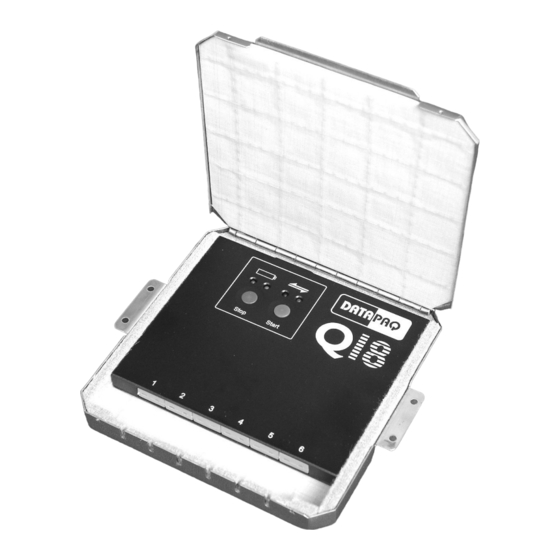
- Page 24 By using the spacer blocks provided with the thermal barrier, the height above and below the carrier frame can be set to suit the dimensions of the process chamber. Q18 data logger in place in TB7400 thermal barrier, for use in anti-reflective- coating processes.
- Page 25 Probe Location and Attachment The method of attaching the probe to the photovoltaic cell will depend on process temperature. At lower temperatures, Kapton tape (p. 12) can be used as a quick way of obtaining reasonable results; the tape will probably have to be replaced after each profile run.
- Page 26 Running a Temperature Profile See p. 17 for general procedure. Preparing the Logger Set the sample interval to 0.5 s. This will give adequate resolution of the data, while a shorter sample interval may result in electrical interference being seen in the results (see p. 22). At a sample interval of 0.5 s or greater, the internal circuits of the logger are configured for maximum interference rejection.
- Page 27 Contact Firing (Metallization) Obtaining optimum performance from a photovoltaic cell depends critically on the contact-firing process. Incorrect temperature profiles will affect contact resistance as well as fill factor and hence directly reduce production yields. Using the SolarPaq system the logger travels through the furnace recording temperature profiles from up to six points on the top and bottom of a test cell, and the process is thus monitored without disrupting normal production.
- Page 28 TB7200 thermal barrier, for use in contact-firing processes (TB7250 is similar). TB7250 Temp °C Duration (mins) Dimensions Height Width Length Weight 23 mm 165 mm 224 mm 1.25 kg 0.9 in. 6.5 in. 8.8 in. 2.8 lb Thermocouples The recommended Datapaq thermocouples are ultra-fine high-temperature (PA1570) or binder-less glass-fiber (PA1144);...
- Page 29 thermal contact. When adjusting the probes, ensure that the overall width of the assembly will not foul the furnace walls or any cell guides fitted to the furnace. The thermocouple cables should be routed together back to the logger and thermal barrier in such a way as to minimize the chance of them catching on the furnace conveyor.
- Page 30 additional thermal mass of the cement will adversely affect temperature measurement. Running a Temperature Profile See p. 17 for general procedure. Preparing the Logger Select the fastest possible sample interval (0.05 s), as this will result in the best resolution of data during the very fast temperature ramp-up and cool- down periods.
- Page 31 Module Lamination The temperature profile that the photovoltaic cell module is subjected to during the lamination process is critical to the correct curing of the EVA adhesive, and as such has a direct effect on the module lifetime. The SolarPaq system is placed into the laminator along with the sheet to be monitored, and the process can thus be monitored without disrupting normal production.
- Page 32 TB7100 thermal barrier, for use in lamination processes. The sections of the protection frame fit closely around the barrier. Thermocouples The lamination process is conducted at temperatures well below 250°C, so flexible PTFE-insulated thermocouples are recommended, e.g. PA0061 (p. 12). Probe Attachment The PA0060 series of thermocouples have a flattened junction and are provided with self-adhesive tape so that they can simply be stuck to the glass surface or...
- Page 33 Installing the Logger in the Thermal Barrier Slide the logger into the thermal barrier and close it, ensuring that the thermocouple cables exit through the cut-out at the base of the hinged door. The barrier should then be placed on a sheet of cardboard or glass and the silicone protection frame placed around the barrier.
- Page 34 Europe & Asia Datapaq Ltd Lothbury House Cambridge Technopark Newmarket Road Cambridge CB5 8PB United Kingdom Tel. +44-(0)1223-652400 Fax +44-(0)1223-652401 sales@datapaq.co.uk North & South America Datapaq, Inc. 3 Corporate Park Dr., Unit 1 Derry, NH 03038 Tel. +1-603-537-2680 Fax +1-603-537-2685 sales@datapaq.com China Datapaq Ltd...
Need help?
Do you have a question about the DATAPAQ SolarPaq and is the answer not in the manual?
Questions and answers