Table of Contents
Advertisement
Quick Links
Solenoid-driven Diaphragm Metering Pump
PZD Series
OPERATION MANUAL
Please read this OPERATION MANUAL carefully before use.
Operating the pump incorrectly in disregard of these instructions
may lead to death, injury and/or cause property damage.
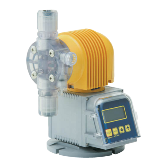
This illustration is for the PZD-30R
7 Thank you for purchasing this TACMINA product. Please read this
OPERATION MANUAL carefully in order to ensure that you will use the
product safely and correctly.
7 Be sure to keep this OPERATION MANUAL in a place where it will be
easily available for reference.
7 If the product you purchased conforms to special specifications not
described in this OPERATION MANUAL, handle the product according to
details of separate meetings, drawings and approved documents.
7 TACMINA accepts no liability whatsoever for any damage caused by
malfunction of this product and other damage caused by use of this product.
www.tacmina.com
Applicable Models
PZD- 30R/60R/100R/
30/60/100/300/500
CLPZD- 30R/60R/100R/
30/60/100
ARPZD-31/61/12
Advertisement
Table of Contents

Related Manuals for Tacmina PZD Series


Summary of Contents for Tacmina PZD Series
- Page 1 30/60/100 ARPZD-31/61/12 This illustration is for the PZD-30R 7 Thank you for purchasing this TACMINA product. Please read this OPERATION MANUAL carefully in order to ensure that you will use the product safely and correctly. 7 Be sure to keep this OPERATION MANUAL in a place where it will be easily available for reference.
- Page 2 • Install the pump in a location that cannot be accessed by anyone but control personnel. CAUTION • If this pump has been dropped or damaged, consult your vender or a TACMINA representative. Using a dropped or damaged pump may result in accidents and/or malfunctions.
- Page 3 • When trouble has occurred (such as when smoke appears or there is a smell of burning), shut down the pump’s operation immediately, and contact your vender or a TACMINA representative. Otherwise, a fire, electric shocks and/or malfunctions may result.
-
Page 5: Table Of Contents
Contents Introduction Checking out the product ......................6 Accessories list ..........................6 Description of product ......................... 9 Names of the parts ........................9 Installation Installing the product ......................... 10 Piping ............................11 ✽ The instructions differ according to the model. Find the model concerned in the table on page 12, and read the instructions given. Connecting .......................... -
Page 7: Checking Out The Product
• Has the pump sustained any damage from vibration or impact during transit? • Have any of the screws come loose or fallen out? Every care is taken by TACMINA in the shipment of its pumps, but if you come across anything untoward, please contact your vender or a TACMINA representative. - Page 8 Accessories list Model w/o relief-valve function for injection of general chemicals: PZD Liquid-end Material VTCE/VTCF Model PVC braided hose (4×9) PVC braided hose (6×11) PVC braided hose (12×18) Hose/tube (3m) PE tube (6×8 PE tube (6×8 or 1/4×3/8) PE tube (9×12 or 3/8×1/2) or 1/4×3/8) Air-release hose (1m) Soft PVC hose (4×6)
- Page 9 Accessories list Model w/ relief-valve function Model w/o relief-valve function for injection of boiler chemicals: PZD for injection of boiler chemicals: PZD Liquid-end Material VTCE Liquid-end Material VTCET Model Model Tube for discharge side (2m) Nylon tube (4×6) Tube for discharge side (2m) Nylon tube (4×6) Tube for suction side (1m) PVC braided hose (4×9)
-
Page 10: Description Of Product
Description of product This is a solenoid-driven diaphragm metering pump with liquid-end parts which are resistant to chemicals and with a compact body. It can be operated on any supply voltage from AC 100V to AC 240V (±10%). Its discharge capacity has been adjusted so that it will remain constant over the supply voltage range. -
Page 11: Installing The Product
Installing the product WARNING • This pump does not have explosion-proof specifications. Do not install it in explosion-proof regions or in explosive or combustible atmospheres. • Install the pump in a location that cannot be accessed by anyone but control personnel. CAUTION •... -
Page 12: Piping
Installing the product (1) Twist the pump head and solenoid-box part (upper part) counterclockwise by about 30 degrees, and lift slightly (by 2 to 3 cm). Twist Solenoid box part (upper part) Wires Circuit box part (lower part) (2) Twist the upper part in the desired direction, align the groove in the coupling of the upper part and the protrusion in the coupling of the lower part, and insert. - Page 13 Provide details on the (1) viscosity of the liquid, (2) length of the pipes (how they are positioned) and (3) specific gravity of the liquid to a TACMINA representative.
- Page 14 Model w/ relief-valve function for injection of general chemicals: PZD-30R/60R/100R Installation is described with an example using a TACMINA tank. • If the valve has not been opened or clogging by foreign matter has occurred inside the pipe at the discharge side of the pump, the chemical will gush out from the relief/air-release port.
- Page 15 Model w/o relief-valve function for injection of general chemicals: PZD-30/60/100/300/500 Installation is described with an example using a TACMINA tank. • It is extremely dangerous for the user to forget to open the valve or for there to be the clogging of foreign matter inside the pump’s discharge-side pipe.
- Page 16 Model w/ relief-valve function for injection of boiler chemicals: PZD-30R Installation is described with an example using a TACMINA tank. • If the valve has not been opened or clogging by foreign matter has occurred inside the pipe at the discharge side of the pump, the chemical will gush out from the relief/air-release port.
- Page 17 Model w/o relief-valve function for injection of boiler chemicals: PZD-30 Installation is described with an example using a TACMINA tank. • It is extremely dangerous for the user to forget to open the valve or for there to be the clogging of foreign matter inside the pump’s discharge-side pipe.
- Page 18 Model w/ relief-valve function for injection of sodium hypochlorite: CLPZD-30R/60R/100R Installation is described with an example using a TACMINA tank. • If the valve has not been opened or clogging by foreign matter has occurred inside the pipe at the discharge side of the pump, the chemical will gush out from the relief/air-release port.
- Page 19 Model w/o relief-valve function for injection of sodium hypochlorite: CLPZD-30/60/100 Installation is described with an example using a TACMINA tank. • It is extremely dangerous for the user to forget to open the valve or for there to be the clogging of foreign matter inside the pump’s discharge-side pipe.
- Page 20 Model w/ automatic air-release function for injection of sodium hypochlorite: ARPZD-31/61/12 Installation is described with an example using a TACMINA tank. • Unlike other models, this pump has a discharge-side joint at the front of the pump head and an air-release side joint on its top.
-
Page 21: Connecting
Provide details on the (1) viscosity of the liquid, (2) length of the pipes (how they are positioned) and (3) specific grav- ity of the liquid to a TACMINA representative who will select the appropriate hose/tube size. • When disconnecting the hose/tube for jobs such as maintenance and then afterwards re-connecting the same hose/ tube, cut about 10 mm off the end of the hose/tube before re-using them. - Page 22 Connecting ■Anti-siphon check valve This pump is provided with an anti-siphon check valve. Use this valve at the injection point unless there is a good rea- son not to do so. Be absolutely sure to install it in the following cases. •...
- Page 23 (1) viscosity of the liquid, (2) length of the pipes (how they are positioned) and (3) specific gravity of the liquid to a TACMINA representative who will select the appropriate tube size. • When disconnecting the tube for jobs such as maintenance and then afterwards re-connecting the same tube, cut about 10 mm off the end of the tube before re-using them.
- Page 24 Connecting ■Anti-siphon check valve This pump is provided with an anti-siphon check valve. Use this valve at the injection point unless there is a good rea- son not to do so. Be absolutely sure to install it in the following cases. •...
- Page 25 (1) viscosity of the liquid, (2) length of the pipes (how they are positioned) and (3) specific gravity of the liquid to a TACMINA representative who will select the appropriate tube size. • When disconnecting the tube for jobs such as maintenance and then afterwards re-connecting the same tube, cut about 10 mm off the end of the tube before re-using them.
- Page 26 Connecting ■Anti-siphon check valve This pump is provided with an anti-siphon check valve. Use this valve at the injection point unless there is a good rea- son not to do so. Be absolutely sure to install it in the following cases. •...
- Page 27 PTFE tube uid, (2) length of the pipes (how they are positioned) and (3) specific gravity of the liquid to a TACMINA rep- resentative who will select the appropriate tube size. • When disconnecting the tube for jobs such as main-...
- Page 28 (2) length of the pipes (how they are positioned) PTFE tube and (3) specific gravity of the liquid to a TACMINA rep- resentative who will select the appropriate tube size. • When disconnecting the tube for jobs such as main-...
- Page 29 (2) length of the pipes (how they are positioned) and (3) specific gravity of the liq- Hose nut uid to a TACMINA representative who will select the appropriate hose size. • When disconnecting the hose for jobs such as maintenance and then afterwards...
- Page 30 • Be sure to securely connect the nylon tube and anti-siphon check valve as well as the anti-siphon check valve and injection point. • The anti-siphon check valve will be corroded by some chemicals, and so such chemicals cannot be used. For special chemicals, consult with a TACMINA representative separately.
- Page 31 Provide details on the (1) viscosity of the liquid, (2) length of the pipes (how they are positioned) and (3) specific grav- ity of the liquid to a TACMINA representative who will select the appropriate hose/tube size. • When disconnecting the hose/tube for jobs such as maintenance and then afterwards re-connecting the same hose/ tube, cut about 10 mm off the end of the hose/tube before re-using them.
- Page 32 Provide details on the (1) viscosity of the liquid, (2) length of the pipes (how they are positioned) and (3) specific gravity of the liquid to a TACMINA representative who will select the appropriate hose/tube size. • When disconnecting the hose/tube for jobs such as maintenance and then afterwards re-connecting the same hose/tube, cut about 10 mm off the end of the hose/tube before re-using them.
- Page 33 Connecting ■Anti-siphon check valve w/ duck-bill cap This pump is provided with an anti-siphon check valve with duck-bill cap. Use this valve at the injection point unless there is a good reason not to do so. Be absolutely sure to install it in the following cases. •...
-
Page 34: Electrical Wiring
Electrical wiring WARNING • This pump cannot be used in explosion-proof regions or in explosive or combustible atmospheres. • Take steps to ensure that the power will not be turned on during the course of work. Hang a sign on the power switch indicating that work is in progress. - Page 35 Electrical wiring Connecting the power supply & protective earth • A 3-pin detachable connector (including the protective earth) is used to connect to the AC power supply. • Use a round tough rubber-sheathed cable as the power cable. (Use VCTF-4C, and cut one.) •...
-
Page 36: Operating Precautions
• When trouble has occurred (such as when smoke appears or there is a smell of burning), shut down the pump’s operation immediately, and contact your vender or a TACMINA representative. Otherwise, a fire, electric shocks and/or malfunctions may result. -
Page 37: Control Panel
Control panel All models: PZD/CLPZD/ARPZD The stroke speed (strokes/min), ratio (%) or discharge volume (mL/min) is set directly on the control panel. STP PS mL/min STOP MODE START SET/RST Part & indicator Description This lights while the power is on, and blinks in synchronization with pump q [PL] lamp operation. -
Page 38: Air Releasing
Air releasing WARNING • During the air releasing, chemical may suddenly gush out from the pipes and other parts. Lead the end of the relief/air-release hose bank to the tank or other container, and secure it so that it will not become disconnected. - Page 39 Air releasing Small type w/ relief-valve function (1) Before proceeding with the air releasing, check that the end of the relief/air-release hose has been led back to the tank or other container. (2) Turn off the pump’s power, and release the pressure inside the discharge-side pipe. (3) Turn on the pump’s power.
- Page 40 Air releasing Small type w/o relief-valve function ✽ excluding 6TCT type (1) Insert the air-release hose provided into the air-release port. (2) Return the other end of the air-release hose to the tank or other container, and secure it firmly. Air- release port...
- Page 41 Air releasing 6TCT type (1) Turn off the pump’s power, and release the pressure inside the dis- charge-side pipe. (2) Loosen slightly the air-release nozzle at the bottom right of the pump head by turning it counterclockwise. Air-release nozzle (3) Insert the hose pump provided, operate the pump, and draw up the chemical until all the air in the pump head comes out.
- Page 42 Air releasing Setting the discharge volume to its maximum level The procedure for setting the discharge volume to its maximum level will be described in the each of the following modes: stroke-speed setting mode, ratio setting mode and discharge-volume setting mode. ■In the stroke-speed setting mode (1) Press the [MODE/SET/RESET] key a number of times until the unit display is set to [spm] (strokes/min).
-
Page 43: Calibration
Calibration About calibration Calibration is a procedure that enables the discharge volume to be set accurately by measuring the maximum dis- charge volume under actual operating conditions at the user’s and storing this volume in the pump’s memory. Example: Calibration is described below using the PZD-30R with a discharge-volume setting of 15 mL/min. (1) Although the discharge volume is set to 15 mL/min, a volume of 16 mL /min will actually be discharged. - Page 44 Calibration Calibration procedure The procedure is described using the PZD-30R as an example. (1) Install the pump and pipes to suit the actual pipe connection conditions for a trial run. (2) Provide a measuring container (such as a graduated measuring cylinder) which can be used to obtain an accurate measurement of the pump’s maximum discharge volume in one minute.
-
Page 45: Setting Flow
Setting flow All models: PZD/CLPZD/ARPZD Power ON Stroke-speed setting mode The stroke speed can be adjusted within a range of 1 to 300 spm (strokes/min) using the keys. ✽ The stroke speed can be changed even while the pump is operating. MODE Ratio setting mode The ratio can be adjusted within a range of 1 to 100%... -
Page 46: Discharge-Volume Setting
Discharge-volume setting All models: PZD/CLPZD/ARPZD The discharge volume can be set by one of the following methods. ■Stroke-speed setting mode ■Ratio setting mode The stroke speed (1 to 300 strokes/min) range is set in The ratio (1 to 100%) range is set in increments of 1%. 1-stroke increments. - Page 47 Discharge-volume setting ■Discharge-volume setting mode The discharge volume (0.1 mL/min to maximum dis- charge volume) range is set in increments of 0.1 mL/min. ✽ Actual control is exercised using the stroke speed so the least increment in which the speed can be con- trolled is the discharge volume per stroke (maximum discharge volume divided by 300).
-
Page 48: Procedure For Prolonged Shutdown Of Operation
Procedure for prolonged shutdown of operation Follow the steps below when shutting down the pump for a prolonged period. To shut down the pump (1) Operate the pump so that clean water or cleaning fluid is sucked in and discharged for about 30 minutes to clean the inside of the pump head. -
Page 49: Maintenance Precautions
• When trouble has occurred (such as when smoke appears or there is a smell of burning), shut down the pump’s operation immediately, and contact your vender or a TACMINA representative. Otherwise, a fire, electric shocks and/or malfunctions may result. -
Page 50: Replacing The Diaphragm
Replacing the diaphragm IMPORTANT • When securing the pump head using the head bolts, tighten them up evenly a little at a time in the sequence shown in the figure on the right. If, for instance, the bolts are tightened up in the sequence of 1 →... -
Page 51: Replacing The Air-Release Nozzle
Replacing the diaphragm IMPORTANT • Replace the protective diaphragm at the same time as the diaphragm. Installing the diaphragm (1) Align the groove in the spacer with the new protective diaphragm, and assemble them properly. (small type only) (2) Fit the new protective diaphragm (with spacer for the small type) into the pump shaft. (3) Align the auxiliary ring at the fixed position shown below, and install it. -
Page 52: Replacing The Valve Seats And Check Balls
Replacing the valve seats and check balls IMPORTANT • Install the parts in the correct sequence and correct directions. • Pay special attention to the sequence and directions for the joints and valve seat assemblies. • Check the O-ring, check balls and valve seats for damage and dirt. Model for injection of general chemicals (small type) Series : PZD Series : PZD... - Page 53 Replacing the valve seats and check balls Series : PZD Series : PZD Model : Small type (30R/60R/100R/30/60/100) Model : Small type (30/60/100) Liquid-end material: FTCT Liquid-end material: 6TCT Cap nut Tube fitting Discharge-side upper joint Discharge-side joint O-ring* (size: P18) Seat packing Valve stopper* Ball stopper...
- Page 54 Replacing the valve seats and check balls Model for injection of general chemicals (large type) Series : PZD Series : PZD Model : Large type (300/500) Model : Large type (300/500) Liquid-end material: VTCE/VTCF Liquid-end material: FTCT Cap nut Discharge-side upper joint Retaining ring O-ring* (size: P18)
- Page 55 Replacing the valve seats and check balls Model for injection of boiler chemicals Series : PZD Series : PZD Model : Large type (300/500) Model : Small type (30R/30) Liquid-end material: STCT Liquid-end material: VTCE Cap nut Push-in joint Discharge-side upper joint O-ring* Ball stopper (size: P18)
- Page 56 Replacing the valve seats and check balls Model for injection of sodium hypochlorite Series : CLPZD Model : Small type (30R/60R/100R/30/60/100) Liquid-end material: ATCF Retaining ring Discharge-side joint Spacer Ball stopper Check ball Valve seat Ball stopper Check ball Valve seat O-ring Pump head (size: P12)
- Page 57 Replacing the valve seats and check balls Model w/ automatic air-release function for injection of sodium hypochlorite Series : ARPZD Model : Small type (31/61/12) Liquid-end material: CL Hose nut Air-release joint Case for duck-bill valve Duck-bill valve Valve seat Spacer Check ball (6.35 mm diameter) Valve seat...
-
Page 58: Replacing The Relief Valve
Replacing the relief valve IMPORTANT Take the following action when the relief-valve function has been activated by clogging of the discharge- side pipe, for instance. • Shut down the pump immediately, remove the cause of the trouble, and take steps to prevent its recurrence. -
Page 59: Troubleshooting
• When trouble has occurred (such as when smoke appears or there is a smell of burning), shut down the pump’s operation immediately, and contact your vender or a TACMINA representative. Otherwise, a fire, electric shocks and/or malfunctions may result. - Page 60 Troubleshooting During operation Cause Remedy Trouble The pump Air has (1) A liquid which easily vaporize is being used. (1) Dilute the liquid. runs, but found its (2) Air has entered from a joint or seal to (2) Tighten the parts from which the liquid is leaking. no liquid is way inside.
-
Page 61: Model Code
Model code Not all model combinations are possible. When selecting the pump model, first check "Liquid-end material" and "Specification". Model for injection of general chemicals Model for injection of boiler chemicals 30R - VTCE 4×9PVC VTCET 4×6PA (1) Model (discharge volume standard) (1) Model (discharge volume standard) Model Discharge volume... - Page 62 Model code Model for injection of sodium hypochlorite Model w/ automatic air-release function for injection of sodium hypochlorite CLPZD ARPZD ATCF 4×9PVC 4×9PVC (1) Model (discharge volume standard) (1) Model (discharge volume standard) Model Discharge volume Model Discharge volume 30 mL/min (w/ relief-valve function) 30 mL/min 60 mL/min (w/ relief-valve function) 60 mL/min...
-
Page 63: Liquid-End Material
Liquid-end material Model w/ Model Model Model automatic for injec- for injec- air-release tion of tion of Model for injection of general chemicals function for boiler sodium injection chemi- hypo- of sodium cals chlorite hypochlorite Part VTCE VTCF FTCE FTCF FTCT 6TCT STCT... -
Page 64: Specification
Specification Model w/ relief-valve function for injection of general chemicals: PZD (small type) 100R Model Specification VTCE VTCF FTCE FTCF FTCT VTCE VTCF FTCE FTCF FTCT VTCE VTCF FTCE FTCF FTCT Max. discharge volume* Max. discharge 0.7* pressure* Stroke speed 1 to 300 strokes/min (digital setting) Stroke length Fixed at 1.0 mm... - Page 65 Specification Model w/o relief-valve function for injection of general chemicals: PZD (small type) Model Specification VTCE VTCF FTCE FTCF FTCT 6TCT VTCE VTCF FTCE FTCF FTCT 6TCT VTCE VTCF FTCE FTCF FTCT 6TCT Max. discharge volume* Max. discharge pressure* Stroke speed 1 to 300 strokes/min (digital setting) Stroke length Fixed at 1.0 mm...
- Page 66 Specification Model for injection of general chemicals: PZD (large type) Model Specification VTCE VTCF FTCT 6TCT VTCE VTCF FTCT 6TCT Max. discharge volume* 21.6 19.8 32.4 30.6 Max. discharge pressure* Stroke speed 1 to 300 strokes/min (digital setting) Stroke length 0.3 to 1.5 mm (manual dial) 12×18 12×18...
- Page 67 Specification Model for injection of boiler chemicals: PZD Model Specification VTCET VTCET Max. discharge volume* 1.68 Max. discharge pressure* Stroke speed 1 to 300 strokes/min (digital setting) Stroke length Fixed at 1.0 mm Discharge 4×6 side (nylon tube) Connection 4×9 (hose/tube: Suction side (PVC braided hose)
- Page 68 Specification Model for injection of sodium hypochlorite: CLPZD Model 100R Specification Max. discharge volume* Max. discharge 0.7* pressure* Stroke speed 1 to 300 strokes/min (digital setting) Stroke length Fixed at 1.0 mm 4×9 4×9 6×11 6×11 Discharge (PVC braided (PVC braided (PVC braided hose), (PVC braided hose), side...
- Page 69 Specification Model w/ automatic air-release function for injection of sodium hypochlorite: ARPZD Model Specification Max. discharge volume* 3.42 5.58 Max. discharge pressure* Stroke speed 1 to 300 strokes/min (digital setting) Stroke length Fixed at 1.0 mm 4×9 6×11 Discharge (PVC braided hose), (PVC braided hose), side 6×8...
-
Page 70: Performance Curve
Performance curve • The performance curves below represent the measurements taken under the conditions prevailing at TACMINA’s test facilities, and are provided here as examples. • The individual conditions prevailing on-site and differences between models may produce minor variations from these curves. - Page 71 Performance curve Model for injection of general chemicals: PZD (large type) PZD−300− PZD−500− VTCE/VTCF VTCE/VTCF Conditions: clean water, room temperature Conditions: clean water, room temperature 0.1MPa 0.1MPa 0.3MPa 0.2MPa 50 100 150 200 250 300 50 100 150 200 250 (spm) (spm) Stroke speed (strokes/min)
- Page 72 Performance curve Model for injection of sodium hypochlorite: CLPZD ■Model w/ relief-valve function CLPZD−30R− CLPZD−60R− CLPZD−100R− ATCF ATCF ATCF Conditions: clean water, room temperature Conditions: clean water, room temperature Conditions: clean water, room temperature 0.2MPa 0.2MPa 0.2MPa 0.7MPa 0.7MPa 0.7MPa 250 300 250 300 (spm)
-
Page 73: External Dimension
External dimension Model for injection of general chemicals: PZD (small type) PZD−30R/60R/100R/30/60/100−VTCE/VTCF Model w/ relief-valve function Model w/o relief-valve function 16.5 φ118 (150) (150) (153.5) PZD−30R/60R/100R/30/60/100−FTCE/FTCF/FTCT Model w/ relief-valve function Model w/o relief-valve function PVDF PVDF 17.5 φ118 (150) (150) (154.5) PZD−30/60/100−6TCT (91) - Page 74 External dimension Model for injection of general chemicals: PZD (large type) PZD−300/500−VTCE/VTCF 24.5 85.5 φ118 (150) (180) PZD−300/500−FTCT φ118 (150) (174.5) PZD−300/500−STCT φ118 (150) (174.5)
- Page 75 External dimension Model for injection of boiler chemicals: PZD PZD−30R/30/VTCET Model w/ relief-valve function Model w/o relief-valve function 16.5 (150) φ118 (150) (153.5) Model for injection of sodium hypochlorite: CLPZD CLPZD−30R/60R/100R/30/60/100−ATCF Model w/ relief-valve function Model w/o relief-valve function 16.5 (150) (150) φ118...
-
Page 76: Consumables
NOTE • TACMINA will continue to supply consumables for its pumps for a period of eight (8) years after the manufacture of the pumps has been discontinued. • “Parts kits” consisting of a complete set of consumables are available (except for some models). - Page 77 Consumables PZD−30/60/100−6TCT Recommended Part Quantity per pump replacement timeframe O-ring Every 10,000 hours Check ball Every 10,000 hours Valve stopper Every 10,000 hours Diaphragm assembly (diaphragm, protective diaphragm, spacer) Every 10,000 hours Air-release valve assembly Every 10,000 hours Model for injection of general chemicals (large type) PZD−300/500−VTCE/VTCF Recommended Part...
-
Page 78: Spare Parts & Options
This phenomenon that the negative pressure inside the pump head causes air bubbles to form, diminishing the dis- charge volume and causing abnormal noises and vibration. ✽ For more detailed information, ask for “How to use metering pumps properly,” a technical document provided by TACMINA. -
Page 79: After-Sales Services
■Minimum retention period for consumables TACMINA will continue to supply consumables for its pumps for a period of eight (8) years after the manufacture of the pumps has been discontinued. - Page 80 EM-112 ( 3 ) 1 2010/7/DDD...
Need help?
Do you have a question about the PZD Series and is the answer not in the manual?
Questions and answers