Table of Contents
Advertisement
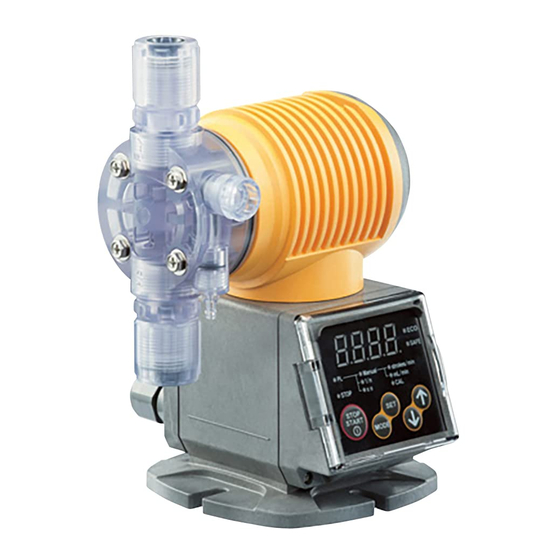
Solenoid-driven Diaphragm Metering Pump
PW Series
OPERATION MANUAL
Please read this OPERATION MANUAL carefully before use.
Operating the pump incorrectly in disregard of these instructions
may lead to death, injury and/or cause property damage.
This illustration is for the PW-30R
7 Thank you for purchasing this TACMINA product. Please read this
OPERATION MANUAL carefully in order to ensure that you will use the
product safely and correctly.
7 Be sure to keep this OPERATION MANUAL in a place where it will be
easily available for reference.
7 If the product you purchased conforms to special specifications not
described in this OPERATION MANUAL, handle the product according to
details of separate meetings, drawings and approved documents.
7 TACMINA accepts no liability whatsoever for any damage caused by
malfunction of this product and other damage caused by use of this product.
www.tacmina.com
Applicable Models
PW/PWM/PWT
DCLPW/DCLPWM/DCLPWT
CLPW/CLPWM/CLPWT
Advertisement
Table of Contents

Related Manuals for Tacmina PW Series


Summary of Contents for Tacmina PW Series
- Page 1 DCLPW/DCLPWM/DCLPWT CLPW/CLPWM/CLPWT This illustration is for the PW-30R 7 Thank you for purchasing this TACMINA product. Please read this OPERATION MANUAL carefully in order to ensure that you will use the product safely and correctly. 7 Be sure to keep this OPERATION MANUAL in a place where it will be easily available for reference.
- Page 2 • Install the pump in a location that cannot be accessed by anyone but control personnel. CAUTION • If this pump has been dropped or damaged, consult your vender or a TACMINA representative. Using a dropped or damaged pump may result in accidents and/or malfunctions.
- Page 3 • When trouble has occurred (such as when smoke appears or there is a smell of burning), shut down the pump’s operation immediately, and contact your vender or a TACMINA representative. Otherwise, a fire, electric shocks and/ or malfunctions may result.
- Page 4 Other Precautions CAUTION • Do not attempt to remodel the pump. • Install a protective barrier or other preventive action to cope with a chemical spill just in case one occurs. Also take steps to ensure that the pump will not get wet from the chemical. •...
-
Page 5: Table Of Contents
Contents Introduction Checking out the product ......................5 Accessories list ..........................5 Description of product ......................... 8 Names of the parts ........................8 Installation Installing the product ........................9 Piping ............................10 Connecting ..........................11 ✽ The instructions differ according to the model. Find the model concerned in the table on page 11, and read the instructions given. Electrical wiring .......................... -
Page 6: Checking Out The Product
• Has the pump sustained any damage from vibration or impact during transit? • Have any of the screws come loose or fallen out? Every care is taken by TACMINA in the shipment of its pumps, but if you come across anything untoward, please contact your vender or a TACMINA representative. - Page 7 Accessories list 6TCT Model Tube (3m) PTFE tube (6×8) Anti-siphon check valve 1 set (R1/2 or R3/8) Foot valve 1 set Hose pump for air-release 1 set Cable Pump-mounting nuts/bolts 2 sets (M5×30) Operation manual 1 copy ■ PW/PWM/PWT (High-viscosity type) VTCF Model Hose (3m)
- Page 8 Accessories list ■ DCLPW/DCLPWM/DCLPWT (For injection of sodium hypochlorite type w/ air block) ATCF Relief-valve function w/ relief valve w/o relief valve Model 100R PVC braided PVC braided Hose (3m) PVC braided hose (6×11) PVC braided hose (6×11) hose (4×9) hose (4×9) Relief/air-release hose (1m) Soft PVC hose (4×6, installed)
-
Page 9: Description Of Product
Description of product This is a solenoid-driven diaphragm metering pump with liquid-end parts which are resistant to chemicals and with a compact body. It can be operated on any supply voltage from AC 100V to AC 240V (±10%). Its discharge capacity has been adjusted so that it will remain constant over the supply voltage range. -
Page 10: Installing The Product
Installing the product WARNING • This pump does not have explosion-proof specifications. Do not install it in explosion-proof regions or in explosive or combustible atmospheres. • Install the pump in a location that cannot be accessed by anyone but control personnel. CAUTION •... -
Page 11: Piping
Installing the product (1) Twist the pump head and solenoid-box part (upper part) counterclockwise by about 30 degrees, and lift slightly (by 2 to 3 cm). ✽ Check whether the O-ring is fitted into place Solenoid box part (upper part) here. -
Page 12: Connecting
• The occurrence of pulsation will cause the pump’s hoses/tubes to vibrate. Secure the hoses/tubes so that they will not swing about. • In order to reduce pulsation, the installation of a damper is recommended. Ask a TACMINA representative for more information. - Page 13 Connecting I. Pump below-tank mounting position (w/ relief valve) II. Pump below-tank mounting position (w/o relief valve) Applicable models:PW /CLPW -30R/60R/100R Applicable models:PW /CLPW -30/60/100/200 Main pipe Main pipe Valve Valve Anti-siphonal check valve Anti-siphonal check valve Relief valve Relief/air-release hose Degassing joint Tank Tank...
- Page 14 Connecting Injection point connections The anti-siphonal check valve has a different shape depending on the material used for the liquid-end material of the pump. First check the model of the pump to be used, and then refer to the applicable diagram below. ✽...
- Page 15 Connecting Foot valve connection The foot valve has a different shape depending on the material used for the liquid-end material of the pump. First check the model of the pump to be used, and then refer to the applicable diagram below. ✽...
- Page 16 Connecting Degassing joint connection (1) Loosen the union nut, and remove the joint and body. (4) Install the union nut on the body. Check that the O-ring is provided on the body, and Joint tighten it up manually. Union nut O-ring O-ring Body...
-
Page 17: Electrical Wiring
Electrical wiring WARNING • This pump cannot be used in explosion-proof regions or in explosive or combustible atmospheres. • Take steps to ensure that the power will not be turned on during the course of work. Hang a sign on the power switch indicating that work is in progress. - Page 18 Electrical wiring There are two cable grounds, one for the power supply and one for the signals. Connecting the power supply & protective earth Connecting the signal cable • A 3-pin detachable connector (including the protective A-6 pin deta chable connector is used to connect to the earth) is used to connect to the AC power supply.
-
Page 19: Operation
Electrical wiring Signal cable distribution ■ When not using a signal distributor ● Pulse signal You can connect multiple instances of this pump in parallel and apply pulse signals and operation/stop signals to the pumps. Model comparison table Pulse signal Operation/Stop signal Pump Pump Approximately 0.5 mA... - Page 20 Electrical wiring External operation and stop input The pump can be turned on and off using signals from an external device such as an interlock or level switch. The pump runs or stops while (5) and (6) are shorted (no-voltage contacts) or while (5)+ and (6)- (open collector) are input.
-
Page 21: Operating Precautions
• When trouble has occurred (such as when smoke appears or there is a smell of burning), shut down the pump’s operation immediately, and contact your vender or a TACMINA representative. Otherwise, a fire, electric shocks and/or malfunctions may result. -
Page 22: Discharge-Volume Setting
Discharge-volume setting This product can be controlled using the three methods described below. (1) Setting the discharge capacity by manual operation (2) Setting the discharge capacity using the stroke length (3) Controlling operation using signal input Methods (1) and (2) are described here. ✽... -
Page 23: Air Releasing
Air releasing WARNING • During the air releasing, chemical may suddenly gush out from the pipes and other parts. Lead the end of the relief/air-release hose bank to the tank or other container, and secure it so that it will not become disconnected. - Page 24 Air releasing Air-release method A Before proceeding with the air releasing, check that the end of the relief/air-release hose has been led back to IMPORTANT the tank or other container. • Under no circumstances must the air-release knob be turned counterclockwise. (1) Turn off the pump’s power, and release the pressure inside the discharge side pipe.
- Page 25 Air releasing Air-release method B (1) Insert the accessory air-release hose (4 mm dia. × (7) While operating the pump, turn the air-release knob 6 mm dia.) into the air-release port. (Ensure that the counterclockwise (toward the left) for between 1 and hose is inserted all the way to its base.) 1.5 turns.
- Page 26 Air releasing Air-release method C (1) Turn off the pump’s power, and release the pressure (4) Close the air-release nozzle by turning it clockwise. inside the discharge-side pipe. (2) Set the stroke-length adjustment dial to the 100% marking on the scale. IMPORTANT •...
-
Page 27: Calibration
Calibration About calibration Calibration is a function that enables the discharge capacity to be set accurately by measuring the maximum discharge capacity under the conditions of actual use by the user and storing the measured value in the pump’s memory. It works only in the discharge capacity setting mode of the PW, DCLPW and CLPW. -
Page 28: Control Panel
Control panel ■ PW series: Standard (pulse-input) type Name Function • This lights while power is supplied. (1) PL LAMP (10) • During operation, it blinks at the timing of the pump’s operation. (2) STOP LAMP This lights while the pump is shut down. -
Page 29: Pump Control Functions
Pump control functions Function correspondence table DCLPW/DCLPWM/DCLPWT Series PW/PWM/PWT CLPW/CLPWM/CLPWT General chemical injection High-viscosity Boiler High-pressure Sodium hypochlorite Model 30R/60R/100R 30/60/100 60/100 30R/60R/100R 30/60/100 ● ● ● Relief-valve function ● ● ● ● ● SAFE mode × × × × ●... - Page 30 Pump control functions Manual mode ● Display ● Basic operation In the manual mode, the discharge capacity can be set When the pump has stopped When settings are established using either of the following methods. Stroke number setting mode Set the stroke number range (1 to 300 strokes/min.) in 1-step increments.
- Page 31 Pump control functions Timer control ● Interval mode ● WEEK mode ON/OFF operations are repeated by setting the ON The pump operates automatically every week at the ON period and OFF period. time and OFF time that have been set for the same day of the week and for the same periods.
-
Page 32: Keylock
Pump control functions Analog input-based proportional control ● Basic operation ● Purposes of operation When the proportional band (straight line gradient) and Analog proportional control is used for proportional set points are set for the analog signals (4 to 20 mA) injection and other uses. -
Page 33: Parameter Settings
Parameter settings Setting flow ✽ For details on how to change the operation mode, refer to the setting flow at the end of this manual. 【Standard (pulse-input) type】 【Analog type】 【Timer type】 Manual mode (strokes/min) Manual mode Manual mode ✽ The parameter settings can be changed using the [ ] and [ ] keys. Parameter settings screen For details on the parameters, refer to the settings list below. -
Page 34: Maintenance Precautions
• When trouble has occurred (such as when smoke appears or there is a smell of burning), shut down the pump’s operation immediately, and contact your vender or a TACMINA representative. Otherwise, a fire, electric shocks and/or malfunctions may result. - Page 35 Maintenance precautions ■ Replacing the relief valve When the relief-valve function has been triggered by blockage of the discharge side pipe or by some other factor, take the following steps. • Immediately stop the pump, remove the cause of the trouble and take steps to prevent recurrence. •...
-
Page 36: Exploded Views Of Liquid-End Parts And External Dimension
Exploded views of liquid-end parts and external dimension General chemical injection type Series: PW/PWM/PWT Model: 30R/30/60R/60/100R/100 Liquid-end material: VTCE/VTCF ■ Exploded views of liquid-end parts Hose nut Retaining ring * Diaphragm assembly Discharge-side joint Protective diaphragm Ball stopper Check ball Diaphragm Valve seat Ball stopper... - Page 37 Exploded views of liquid-end parts and external dimension General chemical injection type Series: PW/PWM/PWT Model: 200 Liquid-end material: VTCE/VTCF ■ Exploded views of liquid-end parts Hose nut Retaining ring * * Diaphragm assembly Protective diaphragm A Discharge-side joint Spacer ring Protective diaphragm B Ball stopper Check ball...
- Page 38 Exploded views of liquid-end parts and external dimension General chemical injection type Series: PW/PWM/PWT Model: 30R/30/60R/60/100R/100 Liquid-end material: FTCE/FTCF/FTCT ■ Exploded views of liquid-end parts Tube fitting * Diaphragm assembly Discharge-side joint Protective diaphragm Ball stopper Check ball Diaphragm Valve seat Ball stopper Check ball Valve seat...
- Page 39 Exploded views of liquid-end parts and external dimension General chemical injection type Series: PW/PWM/PWT Model: 30/60/100 Liquid-end material: 6TCT ■ Exploded views of liquid-end parts Hose nut * Diaphragm assembly Discharge-side upper joint Protective diaphragm * O-ring * Valve stopper Diaphragm *...
- Page 40 Exploded views of liquid-end parts and external dimension High-viscosity type Series: PW/PWM/PWT Model: 60/100 Liquid-end material: VTCF ■ Exploded views of liquid-end parts Hose nut Discharge-side upper joint * Diaphragm assembly * O-ring (P16) * Valve stopper Protective diaphragm * Compressed coil spring Diaphragm *...
- Page 41 Exploded views of liquid-end parts and external dimension Boiler type Series: PW/PWM/PWT Model: 30R/30 Liquid-end material: VTCET ■ Exploded views of liquid-end parts Flareless joint * Diaphragm assembly Joint Protective diaphragm Ball stopper Diaphragm Check ball Valve seat Ball stopper Check ball Valve seat Auxiliary ring...
- Page 42 Exploded views of liquid-end parts and external dimension High-pressure type Series: PW/PWM/PWT Model: 30 Liquid-end material: VTCET ■ Exploded views of liquid-end parts Flareless joint * Diaphragm assembly Protective diaphragm Joint Diaphragm Ball stopper Check ball Valve seat Ball stopper Check ball Valve seat Auxiliary ring...
- Page 43 Exploded views of liquid-end parts and external dimension For injection of sodium hypochlorite type w/ air-block Series: DCLPW/DCLPWM/DCLPWT Model: 30R/30/60R/60/100R/100 Liquid-end material: ATCF ■ Exploded views of liquid-end parts * Diaphragm assembly Retaining ring Protective diaphragm Discharge-side joint Diaphragm Back : Engraved mark “CL” Spacer Ball stopper* Check ball...
- Page 44 Exploded views of liquid-end parts and external dimension For injection of sodium hypochlorite type Series: CLPW/CLPWM/CLPWT Model: 30R/30/60R/60/100R/100 Liquid-end material: ATCF ■ Exploded views of liquid-end parts * Diaphragm assembly Retaining ring Protective diaphragm Discharge-side joint Diaphragm Back : Engraved mark “CL” Spacer Ball stopper* Check ball...
-
Page 45: Troubleshooting
• When trouble has occurred (such as when smoke appears or there is a smell of burning), shut down the pump’s operation immediately, and contact your vender or a TACMINA representative. Otherwise, a fire, electric shocks and/or malfunctions may result. - Page 46 Troubleshooting During operation Description of Description of Cause Remedial action trouble 1 trouble 2 The pump does not turn on. (1) Power supply or voltage trouble. (1) Check the power supply and the voltage, and then (The display does not light.) connect the pump to the correct power supply.
- Page 47 Troubleshooting When the signal input mode is established Description of trouble Cause Remedial action Operation is not per- formed as per the set Place the signal line away from the power line. frequency-division or Noise is being carried on the signal line. Alternatively, use a shielded cable for the sig- magnification (when nal line.
-
Page 48: Specifications
Not all model combinations are possible. When selecting the pump model, first check “Liquid-end material” and “Specification”. ■ Model code VTCE 4X9PVC (1) Series name (5) Hose standard Standard Size Material Used only to inject sodium hypochlorite 4×9 DCLPW In-line automatic air-release type with air block 6×11 PVC Used only to inject sodium hypochlorite 12×18 PVC... -
Page 49: Performance Specifications
■ Performance Specifications ● General chemical injection type Conditions: clean water, room temperature Series PW/PWM/PWT Liquid-end material VTCE/VTCF Model 100R mL/min Max. discharge volume 13.2 Max. discharge pressure MPa Stroke speed strokes/min 1 ~ 300 (Enables setting in 1-stroke units) Stroke length 0.5 ~ 1 (Enables adjustment using the dial) φ4×φ9... - Page 50 ■ Performance Specifications ● High-viscosity type Conditions: clean water, room temperature Series PW/PWM/PWT Liquid-end material VTCF Model mL/min Max. discharge volume Max. discharge pressure MPa Stroke speed strokes/min 1 ~ 300 (Enables setting in 1-stroke units) Stroke length 0.5 ~ 1 (Enables adjustment using the dial) φ12×φ18 Discharge side Connection...
- Page 51 ■ Performance Specifications ● Sodium hypochlorite injection type w/ air block Conditions: clean water, room temperature Series DCLPW/DCLPWM/DCLPWT Liquid-end material ATCF Model 100R mL/min Max. discharge volume Max. discharge pressure MPa Stroke speed strokes/min 1 ~ 300 (Enables setting in 1-stroke units) Stroke length 0.5 ~ 1 (Enables adjustment using the dial) φ4×φ9...
-
Page 52: Liquid-End Material
■ Liquid-end material ● General chemical injection type Series PW/PWM/PWT Model VTCE VTCF FTCE FTCF FTCT 6TCT Pump head PVDF PVDF PVDF SUS316 Diaphragm PTFE PTFE PTFE PTFE PTFE PTFE Check ball Ceramic Ceramic Ceramic Ceramic Ceramic Ceramic O-ring EPDM Fluoro rubber EPDM Fluoro rubber Special fluoro rubber... -
Page 53: Power Supply Specifications
■ Power Supply Specifications 30R/30 30R/30 60R/60 100R/100 (Boiler/ High-pressure type) Rated voltage AC100~240V(±10%) No. of phases 1-phases No. of frequency 50/60Hz Maximum current 2.0A 2.5A Max. power consumption 200VA 250VA Ave. power consumption • Use the maximum current in calculating the required power capacity. •... -
Page 54: Performance Curve
■ Performance curve • The performance curves below represent the measurements taken under the conditions prevailing at TACMINA’s test facilities, and are provided here as examples. • The individual conditions prevailing on-site and differences between models may produce minor variations from these curves. - Page 55 Conditions: clean water, room temperature PW/PWM/PWT-30-6TCT PW/PWM/PWT-200-VTCE/VTCF 0.2MPa 0.2MPa 0.5MPa 100 150 200 250 300 100 150 200 250 300 (strokes/min) (strokes/min) Stroke speed Stroke speed PW/PWM/PWT-60-6TCT ● Boiler type Conditions: clean water, room temperature PW/PWM/PWT-30R/30-VTCET 0.2MPa 0.5MPa 0.2MPa 1.5MPa 100 150 200 250 300 (strokes/min) Stroke speed...
- Page 56 ● Sodium hypochlorite injection type w/ air block ● Sodium hypochlorite injection type Conditions: clean water, room temperature DCLPW/DCLPWM/DCLPWT-30R-ATCF DCLPW/DCLPWM/DCLPWT-30-ATCF CLPW/CLPWM/CLPWT-30R-ATCF CLPW/CLPWM/CLPWT-30-ATCF 0.2MPa 0.2MPa 0.7MPa 1.0MPa 100 150 200 250 300 100 150 200 250 300 (strokes/min) (strokes/min) Stroke speed Stroke speed DCLPW/DCLPWM/DCLPWT-60R-ATCF DCLPW/DCLPWM/DCLPWT-60-ATCF...
-
Page 57: Application Examples
Application examples TACMINA float switch ■ Stopping the pump when the tank has become empty (5) External stop signal (6) COM PW/PWM [Explanation] (1) When the chemical liquid level in the tank drops, the contact signal of the float switch is set to ON. -
Page 58: Consumables
NOTE • TACMINA will continue to supply consumables for its pumps for a period of eight (8) years after the manufacture of the pumps has been discontinued. - Page 59 Consumables (4) PW/PWM/PWT-30/60/100-6TCT Recommended Part Quantity per pump replacement timeframe O-ring (P18) Every 10,000 hours Check ball Every 10,000 hours Valve stopper Every 10,000 hours Diaphragm assembly (diaphragm, protective diaphragm) Every 10,000 hours Air-release nozzle assembly Every 10,000 hours O-ring (S60) Every 10,000 hours (5) PW/PWM/PWT-60/100-VTCF-V (High-viscosity type) Recommended...
- Page 60 Consumables (8) DCLPW/DCLPWM/DCLPWT-30R/60R/100R/30/60/100-ATCF Quantity per pump Recommended Part replacement timeframe 30R/60R/100R 30/60/100 Valve seat assembly (Discharge-side) Every 10,000 hours Valve seat assembly (Suction-side) Every 10,000 hours Diaphragm assembly (diaphragm, protective diaphragm) Every 10,000 hours Relief valve – Every 10,000 hours* Air-release knob –...
-
Page 61: Spare Parts & Options
This phenomenon that the negative pressure inside the pump head causes air bubbles to form, diminishing the dis- charge volume and causing abnormal noises and vibration. ✽ For more detailed information, ask for “How to use metering pumps properly,” a technical document provided by TACMINA. -
Page 62: After-Sales Services
■Minimum retention period for consumables TACMINA will continue to supply consumables for its pumps for a period of eight (8) years after the manufacture of the pumps has been discontinued. - Page 68 EM-127 ( 8 ) 03 2014/11/DDD...
Need help?
Do you have a question about the PW Series and is the answer not in the manual?
Questions and answers