
Related Manuals for Tense TDK-96

Summary of Contents for Tense TDK-96
- Page 1 ELEKTRİK - ELEKTRONİK SAN.TİC.A.Ş. TDK-96 and TDK-96H SUBMERSIBLE PUMP CONTROL RELAY USER MANUAL Work without Total Working Number of TR/EN Energy Error Electrode Hours Stop/Start Menu Language Meter Logs www.tense.com.tr...
- Page 2 Index About Device Device Maintenance Specifications Warnings Considerations in Current Transformer Connection Introduction of Screen and Buttons Connection Diagram Measurement Screens Menu Screens Current Menu Voltage Menu 10-11 Electrode Menu 12-13 Advanced Setting Menu 13-15 Expert Setting Menu Alarm Relay Assigment Changing the Password to Enter the Menu Voltage Asymmetry Current Asymmetry...
-
Page 3: About Device
About Device Submersible pump control relays are designed to control submersible pumps and motors used in wells and similar places, and to protect them from adverse situations that may arise from waterless operation, high or low voltage and current. Device Maintenance Power off the device and disconnect it from the connections. - Page 4 Warnings Use the device in accordance with the instructions given by us. In order not to damage the LCD screen, be careful not to get direct sunlight. After the device is mounted, leave a space of at least 10 cm behind it. Fix the device to the front cover of the panel with the apparatus in the box.
-
Page 5: Connection Diagram
Connection Diagram TANK WELL External Control Common Start Button Start Input Alarm Signal Stop Button Stop Lamp Input Do not apply energy to the electrode (well and tank) and start-stop inputs. Neutr. -
Page 6: Measurement Screens
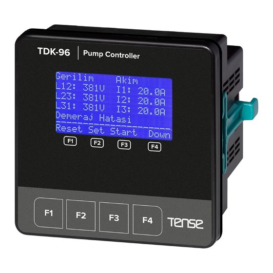
Measurement Screens Voltage Current Active(P) Apparent(S) Active Energy(+²P) L12: 380V I1: 10.1A L1:0.800kW 0.800kVA L1: 0123456789.123kWh L23: 380V 100A L2:38.00kW 10.00kVA L2: 0123456789.123kWh DOWN DOWN L31: 380V I3: 1000A L3:380.0kW 100.0kVA L3: 0123456789.123kWh r:0.99 s:0.99 t:0.99 r:0.99 s:0.99 t:0.99 T : 01234567890123kWh _____________________ _____________________ _____________________... - Page 7 Entering Settings: When the SET button is pressed while on any measurement page, the PASSWORD page (Figure-2) is displayed to enter the menu. While on this page, press the SET button to enter the menu. (The password value is "0000" by default. If the password has been changed by the user, the password specified by the user must be used to enter the menu.) For password entry, you can switch between the steps with the RIGHT button.
- Page 8 Settings Current Menu High Current Error Entrance Delay It determines the time the device will wait before stopping Menu 1.2 the pump when it enters a high current error. High Current Error Entrance Delay To change this value, press the SET button while the High 5 Sc.
- Page 9 Settings Current Menu Low Current Auto Reset Delay It determines the time the device will wait for the pump to Menu 1.7 restart (reset) after entering a low current error. Low Current Auto To change this value, press the SET button while the Low Reset Delay Current Auto Reset Delay page is on the screen.
- Page 10 Settings Voltage Menu It is the second menu that appears after you enter the Menu 2.0 settings page. In this menu, high/low voltage set values, error VOLTAGE MENU delays, automatic reset delays, voltage asymmetry set value and phase sequence active/passive set value settings can be set.
- Page 11 Settings Voltage Menu Low Voltage Error Entrance Delay It determines the time the device will wait before stopping the Menu 2.5 pump when it enters a low voltage error. Low Voltage Error To change this value, press the SET button while the Low Entrance Delay Voltage Error Entrance Delay page is on the screen.
- Page 12 Settings Electrode Menu It is the third menu that appears after you enter the Menu 3.0 settings page. In this menu, electrode set value, well and ELECTRODE MENU storage electrode reading values, electrode delay times, high/low cosine set values, cosine automatic reset delays set value settings can be set.
- Page 13 Settings Electrode Menu Tank Electrode Delay Time It determines the time the device will wait to stop the pump Menu 3.5 after the liquid level in the tank reaches the upper electrode. Tank Electrode Delay This feature allows the pump to run more efficiently and also Time supports two-electrode usage.
- Page 14 Settings Advanced Setting Menu It is the fourth menu that appears after you enter the Menu 4.0 settings page. In this menu, start (first power-on) time, ADVANCED SETTING MENU Modbus RTU communication settings, start/stop memory, star waiting time, panel control feature, alarm relay assignment set value settings can be made.
- Page 15 Settings Advanced Setting Menu Alarm Relay Assignment It provides output from the alarm contact related to Menu 4.5 voltage, current, cosine, well empty and tank full states Alarm Relay Assign. (whichever is selected). To change this value, press the SET button while the Alarm Relay Assing.
-
Page 16: Factory Default Reset
Settings Expert Setting Menu Current Error Logs It shows how many times the pump connected to the Menu 5.2 device has error depending on the current. (High current Current Error Logs (high current + inrush), low current and current asymmetry High Current :0000 error numbers are displayed separately.) Low Current... - Page 17 Settings Expert Setting Menu About Device It is the menu where information about the device is Menu 5.9 accessed. Tense Electronics You can access the device model and software version TDK-96H number on this screen. Version : 1.000 _____________________ Down...
- Page 18 Changing the Password to Enter the Menu It allows to change the password to enter the menu. If the password is Menu 5.7 not changed, the default password is “0000”. Change Password To change this value, press the SET button while the Change Password page is on the screen.
- Page 19 Demurrage Current Control The time taken until the pumps resist the connected load and reach Menu 1.9 the nominal current levels each time they are started is called the Demurrage Multiplier demurrage time and the highest current value in this time is called the demurrage current.
- Page 20 Well Control A well is simply a source of water (lake, pond, river, etc.). Generally, 3 electrodes WELL are used for the device to detect the presence of water in the well. If the electrode reading (Menu 3.2) is below the electrode set (Menu 3.1) value, there is water, and if it is above it, there is no water.
-
Page 21: Factory Values
Factory Values Factory Min. Max. Increase Setting Setting Name Hysteresis Unit Value Value Value Value Code 1.1.0 High Current Set Value 50.0 250.0 High Current Error 1.2.0 sec. Entrance Delay High Current Auto 1.3.0 Off/1 9999 sec. Reset Delay High Current Auto 1.4.0 Off/1 times... - Page 22 Fabrika Çıkış Değerleri Factory Min. Max. Increase Setting Setting Name Value Hysteresis Unit Value Value Value Code Electrode Set Value 3.1.0 Well Electrode Delay Time 3.3.0 6000 sec. Tank Electrode Delay Time 3.5.0 sec. Low Cosine Set Value 3.6.0 Off/0.10 0.99 0.01 Low Cosine Error...
-
Page 23: Technical Specifications
Dimensions Cable mounting Cable mounting Technical Specifications TDK-96 (CT-300) TDK-96H (CT-300) Operating Voltage 400V AC (L2-L3) Operating Frequency 50/60Hz. Operating Temperature -20°C..55°C Operating Power <6VA Operating Current Range 1A - 250A AC 50/60 Hz. Panel Hole Sizes 92 x 92 mm. - Page 24 QUALITY SOLUTIONS MADE IN TÜRKİYE ELEKTRİK - ELEKTRONİK SAN.TİC.A.Ş. Energy and Compensation Tracking System Rev:1.00_010322 www.tenseenerji.com Document Number: DK-112-1...
Need help?
Do you have a question about the TDK-96 and is the answer not in the manual?
Questions and answers