Table of Contents
Advertisement
Quick Links
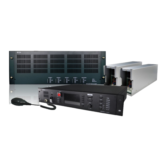
MATRIX CONTROLLER
PEERING FRAME
POWER AMPLIFIER MODULE 250W
Thank you very much for purchasing TOA VX-1000 series product.
Please read the instructions in this manual carefully, to ensure long-term, trouble-free operation of the
system.
INSTRUCTION MANUAL
500W
VX-1000MC
VX-1000PF
VX-1250DA
VX-1500DA
Advertisement
Table of Contents

Subscribe to Our Youtube Channel
Related Manuals for Toa VX-1000MC


Summary of Contents for Toa VX-1000MC
- Page 1 INSTRUCTION MANUAL MATRIX CONTROLLER VX-1000MC PEERING FRAME VX-1000PF POWER AMPLIFIER MODULE 250W VX-1250DA 500W VX-1500DA Thank you very much for purchasing TOA VX-1000 series product. Please read the instructions in this manual carefully, to ensure long-term, trouble-free operation of the system.
-
Page 2: Table Of Contents
2 PRODUCT INTRODUCTION............5 Overview .......................... 5 Interface Description ......................6 3 WIRING ..................12 VX-1000MC Matrix Controller Wiring Diagram .............. 12 VX-1500DA/VX-1250DA Power Amplifier Module Installation Diagram ......13 Reference Size(unit:mm) ..................14 4 INSTRUCTIONS ................15 WEB Page Parameters Configure ................. 15 VX-1000 Configuration tool operating instructions............ -
Page 3: Safety Precautions
• Should the following irregularity be found during use, immediately switch off the power, disconnect the power supply plug from the AC outlet and contact your nearest TOA dealer. Make no further attempt to operate the unit in this condition as this may cause fire or electric shock. - Page 4 • Contact your TOA dealer as to the cleaning. If dust is allowed to accumulate in the unit over a long period of time, a fire or damage to the unit may result.
-
Page 5: Product Introduction
2 PRODUCT INTRODUCTION 2.1 Overview Matrix controller (VX-1000MC) can broadcast general paging and emergency broadcasting liked with fire alarm system. This system is suitable for middle size of the buildings such as factories, schools, hospitals, shopping malls etc., as Public Address system and Emergency broadcasting system. -
Page 6: Interface Description
2.2 Interface Description 2.2.1 VX-1000MC Matrix Controller [ Front ] ① Paging Microphone Interface: Connect the paging microphone (PM-100VX-EA) to this interface, used for general broadcasting and emergency broadcasting. ② CPU OFF Key: Switch to the OFF position means that the paging microphone channel is open; switch to the ON position means that the paging microphone channel is closed (Note: when the CPU is down, please manually switch to OFF to enable). - Page 7 Status LED Introduction Two-color lights, orange light without power input, green light with power AC POWER IN A input. Two-color lights, In case surveillance function is enable: if there is no power input, lights AC POWER IN B orange, if there is power input, lights green; In case surveillance function is disable: if there is no power input, no lights, if there is power input, lights green.
- Page 8 PA IN: 4 power amplifier inputs + 1 backup power amplifier input, used to connect the 100V amplifier output port of any amplifiers. 1 cascade power amplifier input (used when two matrix controllers are cascaded), used to connect the cascade power amplifier input of another Matrix Controller (VX-1000MC). (H: hot end, C: cold end).
- Page 9 Line sequence and definition of control input / control output interface: ① Name Color Pair Description Assignment ② Orange/White COM 1 Common 1 ③ Orange NO 1 Normally Open 1 ④ Green/White COM 2 Common 2 ⑤ CTRL_OUT Blue COM 3 Common 3 ⑥...
- Page 10 2.2.2 VX-1000PF Peering Frame [ Front ] Name LED light status Green light when there is power input, and does not light up when there is no AC POWER IN A power input. Green light when there is power input, and does not light up when there is no AC POWER IN B power input.
- Page 11 ⑥ AC POWER IN B: connect to AC220V – 240V power supply. ⑦ MC-PF LINK: Connected to the MC-PF LINK interface of the Matrix Controller (VX-1000MC), it can detect the power failure of the Peering Frame (VX-1000PF). ⑧ Ground: connect the ground wire.
-
Page 12: Wiring
3 WIRING 3.1 VX-1000MC Matrix Controller Wiring Diagram... -
Page 13: Vx-1500Da/Vx-1250Da Power Amplifier Module Installation Diagram
3.2 VX-1500DA/VX-1250DA Power Amplifier Module Installation Diagram Installation steps Step 1 : Remove the four M3 * 10 countersunk screws on the panel of the Peering Frame, and then remove the panel. Step 2 : Loosen the thumb screw (no need to completely unscrew it, the lock piece can be dropped to the lower right), and turn the lock piece to the lower right (hook down). -
Page 14: Reference Size(Unit:mm
3.3 Reference Size(unit:mm) 3.3.1 VX-1000MC Matrix Controller 3.3.2 VX-1000PF Peering Frame... -
Page 15: Instructions
4.1 WEB Page Parameters Configure 4.1.1 Web Interface Login (1) Enter the IP address (Factory Default IP is 192.168.1.101) of the Matrix Controller (VX-1000MC) in the browser address bar, then press the Enter key. (2) Enter the user name and password (Defaults are both “admin”) in the login window of the Web interface. - Page 16 4.1.2 Status In this web page, users can check terminal ID, terminal IP address, subnet mask, etc. At same time they can check terminal status, real-time value of loudspeaker circuit, real-time value of noise, system date etc. 4.1.3 Network Parameters Set the network parameters, please modify the parameters according to the live environment, save setting, and restart the device to take effect.
- Page 17 4.1.4 Sip (SIP protocol) Set server platform parameters for terminal login. Save after setting, restart the device to take effect. SIP parameter configuration as per the following, SIP server IP address of the terminal, please input right SIP server IP SIP server address or domain name, do not modify without any special situation (the defaults is 5060).
- Page 18 4.1.6 Surveillance Set the reference horn detection value of the four-way loop according to the real-time value of loop detection in the running state. After the modification is complete, click [Save] and restart the device to take effect. In the process of terminal operation, when the real-time value of loop detection is less than the reference loop horn detection value set, the terminal will report the loop detection fault.
- Page 19 4.1.9 Firmware Upgrade (Note: Do not upgrade the firmware unless there's a special need) Click the “Select” button, select the firmware upgrade file provided by the manufacturer, then click the “upgrade” button to start upgrade. (Do not power off during the upgrade process, otherwise it may cause the upgrade failure and equipment failure) 4.1.10 Restore Factory Default Settings Factory reset: all parameters were restored to factory setting.
- Page 20 4.1.11 Reboot Click “Reboot” button can manually reboot the device, some of the parameters modification in the Web page will only take effect after rebooting the device. 4.1.12 Log Matrix Controller can record the operating condition and form log, the user can browser the system log in web page.
-
Page 21: Vx-1000 Configuration Tool Operating Instructions
4.2 VX-1000 Setting Software Operating Instructions 4.2.1 Software Installation Double-click the “VX-1000 Setting Software” installer and press "Next" to install. After the installation is complete, select "Run as administrator" software. 4.2.2 Basic parameter settings (1) New project file:Click "File"-"New" in the main interface of the software, enter the project name in the pop-up dialog box, and create a new project file. - Page 22 (2) Add Unit:In the "Unit List" interface, add units, set unit’s IP and other operations. After the configurations are completed, the system will save configurations automatically. (3) Add VX-1010ZE: Set the number of Zone Expander VX-1010ZE. If the VX-1010ZE is not connected, then you do not need to set this parameter.
- Page 23 (4) Unit Configuration:After units are added, the names of the input and output channels and control input and output channels of each Matrix Controller can be customized in the unit configuration interface. After the configurations are completed, the system will save configurations automatically. The configuration of the Matrix Controller is described as follows: i.
- Page 24 (5) Prepare Audio Files:Click the "Add" button in the "Audio Files" to add audio files (used as a broadcast source). After the configurations are completed, the system will save configurations automatically. (6) Playlist Setting:Set the broadcast audio file playlist (need to add audio files in the "Audio Files" in advance).
- Page 25 (7) Set audio source priority: Set the audio source type (BGM/General/Emergency) and priority of the unit input channel and playlist. After the configurations are completed, the system will save configurations automatically. (8) Set Control Output Pattern: On the “Control Output Pattern Setting” interface, multiple control output can be combined to one group.
- Page 26 (9) Set Zone Pattern:Enter the “Zone Pattern Setting” interface, create zone patterns which can consist of zones and control outputs. After the configurations are completed, the system will save configurations automatically. (10) Set Broadcast Pattern:Enter the “General Pattern Setting” interface, create broadcast patterns which consists of audio source, zones and control outputs.
- Page 27 4.2.3 Set the timer to start broadcasting On the "Timer Program Setting" interface, set the Timer Program name, select “General Pattern”, set “Timer type”, “Start Date”, etc. When the unit reaches the specified time, it will start the specified broadcast pattern. 4.2.4 Set Event to start broadcasting On the "Event Settings"...
- Page 28 4.2.5 Set Preset-Key to start broadcast On the "MC Settings" interface, you can set the general pattern corresponding to the [Preset 1]-[Preset 3] keys of the Matrix Controller. Press the unit's [Preset 1] - [Preset 3] key to start the specified general pattern. 4.2.6 Set Remote Microphone function On the "RM Settings"...
- Page 29 Extension unit Set the number of extension units connected to the remote setting microphone, and support up to 9 extension units. PTT mode: When broadcasting, press the selection key first, and then continue to hold the Broadcast key, then you can initiate a call. Release the Broadcast key to end the broadcast.
- Page 30 4.2.7 Upload configuration After the parameters are modified and saved, you must click [Communication]-[Upload], check the relevant unit in the pop-up dialog box, and then click the "Upload" button to upload the configured data file to the specified unit to take effect.
-
Page 31: Initiate Broadcast
4.3 Initiate broadcast 4.3.1 Audio broadcasting (1) Rotate the [OPERATE Key] to select the target input (4 audio inputs, only single selection), press the [OPERATE Key] to confirm the selection; (2) Rotate the [OPERATE Key] or press the corresponding partition key to select the target output (support multiple selection), press the [OPERATE Key] to confirm the selection;... - Page 32 (4) Additional broadcasting (maximum support for simultaneous 4-channel broadcasting): iii. Rotate the [OPERATE Key] on the interface during the broadcast, select "Add broadcast", and press the [OPERATE Key] to confirm the selection. iv. Select the target input and output (the operation method is the same as above), press [START Key] to initiate the second broadcast.
- Page 33 4.3.3 Preset broadcasting (1) Press the device [preset 1/2/3 key], the corresponding preset status light is green, and the preset broadcast set by the VX-1000 Setting Software is played; (2) Press the corresponding [preset 1/2/3 key] again to end the preset broadcast, the corresponding preset status light is off.
-
Page 34: Monitoring
4.4 Monitoring (1) Press the [AUDIO MONITOR Key], the monitor status light is steady green, and the device enters the monitor state. (2) Rotate the [OPERATE Key] to select the monitor input audio source or zone output audio (Note: only one target can be monitored at the same time). (3) Press the [START Key] to start monitoring, the built-in monitoring speaker plays the target audio for monitoring. -
Page 35: System Menu
4.5 System menu 4.5.1 Volume Adjustment (1) Press the [MENU Key] to enter the system menu interface, rotate the [OPERATE Key], select the "Volume adjustment" module, press the [OPERATE Key] to confirm the selection. (2) Rotate the [OPERATE Key] to select the volume of the target area, and press the [OPERATE Key] to confirm the selection. -
Page 36: Troubleshooting
5 TROUBLESHOOTING 5.1 Troubleshooting 5.1.1 Manually initiate a sound source broadcast without sound? (1) Check whether the device audio source input interface or auxiliary audio source input interface has audio input. Press the monitor key to monitor the audio source input channel, whether there is sound output from the left speaker on the front panel;... - Page 37 Step 1:Using a Phillips screwdriver (or electric screwdriver), remove all 9pcs of M3*5 countersunk countersunk screws on the side and back of the device and remove the upper cover. Step 2:Use a Phillips screwdriver (or electric screwdriver) to remove the four M3*4 countersunk cross screws on the right side bracket of the device and remove the right side bracket.
- Page 38 Step 3 : Locate the button battery at the J8 position on the lower motherboard, and use tweezers to remove the battery and replace it. Battery Step 4:Reinstall the removed bracket and cover.
-
Page 39: Appendix
6 APPENDIX 6.1 Specification 6.1.1 VX-1000MC Matrix Controller Model VX-1000MC AC POWER IN A/B:AC220-240V,50Hz/60Hz,European standard Power Supply terminal Power Consumption 16.65W 4 Channels,European standard terminal,Balanced,Input Audio Input impedance 10KΩ,Rated input 0dB 4 Channels,RCA Terminal,Unbalanced,Input impedance 10KΩ, Auxiliary audio input Rated input 0dB;Mixing with audio input interface Amplifier Interface 4 Channels,RJ45 Interface... - Page 40 6.1.2 VX-1000PF Peering Frame Model VX-1000PF AC POWER IN A/ B:AC220V-240V,50Hz/60Hz,European standard Power Supply terminal Power Consumption 3.5W(When the main power port & power amplifier unit is not inserted) Digital Amplifier Unit slot 4 channels Stand-by Amplifier Unit slot 1 channel Operation temperature -10℃~+55℃...
- Page 41 Traceability Information for Europe Manufacturer: Authorized representative: TOA Corporation TOA Electronics Europe GmbH 7-2-1, Minatojima-Nakamachi, Chuo-ku, Kobe, Hyogo, Japan Suederstrasse 282, 20537 Hamburg, Germany URL: https://toa.com.sg/ 20221102 TOA Corporation...
Need help?
Do you have a question about the VX-1000MC and is the answer not in the manual?
Questions and answers