Advertisement
2003 International Currency Technologies Corporation
Vol. 7.0
Part Number
H4458F
A6&V6 Series
Installation Guide
4 - Way Acceptance
Low Maintenance
Easy Installation
Re - Programmable
Flash ROM
Auto Self -Adjusting
Sensor System
International Currency Technologies
43010 Osgood Rd. Fremont, CA 94539
T el
(510) 353-0289
Fax
(510) 353-0399
E-mail
sales@ict-america.com
Website
www.ict-america.com
Advertisement

Related Manuals for ICT Bill Validator A6 Series


Summary of Contents for ICT Bill Validator A6 Series
- Page 1 Easy Installation Re - Programmable Flash ROM Auto Self -Adjusting Sensor System International Currency Technologies 43010 Osgood Rd. Fremont, CA 94539 T el (510) 353-0289 (510) 353-0399 E-mail sales@ict-america.com Website www.ict-america.com 2003 International Currency Technologies Corporation Vol. 7.0 Part Number H4458F...
-
Page 3: Table Of Contents
Contents Contents (1) A6 / V6 Bill Validator Specifications ......2 (2) Bill Validator Dimensions ........... 2 (3) LED Display ............... 4 (4) LED Status ..............4 (5) Download and upgrade ..........4 (6) A6 Pin-out Assignments : 6-1 S.T.D Pulse for 12 V DC ........5 6-2 S.T.D Pulse for 117 V AC ........ -
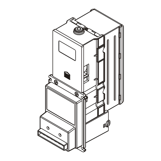
Page 4: A6/V6 Bill Validator Specifications
24V AC 1.5Amp (60HZ) (including bill stacking) Interfaces Power Consumption S.T. D. Pulse Max 50 watts M.D.B. (Multi-Drop Bus) Environment Range ICT Protocol Operating Temperature 0 C~55 C Bill box Capacity Storage Temperature -30 C~70 C 115.0(4.53") 300bills 50.8(2.00") 130.0(5.12") 500bills 94.0(3.70") Approx. -
Page 5: Led Display
(6) 6-1 A6 Pin-out Assignments (S.T.D. Pulse for 12V DC) (3) LED Display The two LED lights located at the front of the unit will show the operational For the 12V DC version of the A6 bill validator, the harness(part no. WEL-M007, status of the bill validator. - Page 6 (6) 6-2 (7) 7-1 A6 Pin-out Assignments (S.T.D. Pulse for 117V AC) V6 Pin-out Assignments (M.D.B. System for 34V DC) For the 117V AC version of the A6 bill validator, connect the 30-pin peripheral For the MDB interface V6 bill validator, connect the 30-pin peripheral connector connector on one end of the harness (part no.
-
Page 7: A6 Pin-Out Assignments (I.c.t. Protocol)
(8) A6 Pin-out Assignments (I.C.T. Protocol) The cable for ICT Protocol ( part no. WEL-V706, see page. 17 for pin-out information connector on one end and a 9-pin PC connector on the other end. To connect, plug the RJ-45 connector into the RJ-45 socket on the side of the BA and connect the 9-pin PC connector to the COM port of a PC (Figure 2). - Page 8 - 10 - - 11 -...
- Page 9 - 12 - - 13 -...
- Page 10 - 14 - - 15 -...
- Page 11 - 16 - - 17 -...
Need help?
Do you have a question about the Bill Validator A6 Series and is the answer not in the manual?
Questions and answers