
Related Manuals for BuckMaster Blue Ridge Bent Back Glider

Summary of Contents for BuckMaster Blue Ridge Bent Back Glider
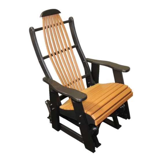
- Page 1 Blue Ridge Bent Back Glider Instruction Manual P/N: FF-BRSG Buck Stove, New Buck Corp |200 Ethan Allen Dr, Spruce Pine, North Carolina 28777, United States | (828) 765-6144 | www.buckstove.com...
-
Page 3: Included Hardware
Included Hardware 2.5in Bolt 3in Bolt 3.5in Bolt Washer 4PCS 2PCS 4PCS 18PCS 10PCS 1.25in Screw 2 in Screw 1 in 8PCS Screw *Hardware without piece count comes preinstalled... -
Page 4: Included Parts
Included Parts Arm/Leg Assembly Back Assembly Seat Assembly Rear Cover Strip Glide Assembly Front/Rear Brace... -
Page 5: Required Tools
Required Tools 7/16 Socket Wrench Socket 7/16 Wrench Wrench #2 Square Bit... - Page 6 Assembly Instructions Step 1 Unscrew the loosely attached 1.25 in(F) & 1 in(N) screws, and remove the rear cover strip (K) and place aside for final assembly. Step 2 Begin the assembly process by placing the glider in the orientation shown to the right, with the back (I) and seat assembly (J) on their side.
- Page 7 Step 3 Align the holes on the arm assembly (H) with the holes going through the back (I) and seat assemblies(J). Step 4 Insert the 3.5 inch bolt (C) through a washer (D) and into the leg/arm (H), back (I) and seat (J) assemblies.
- Page 8 Step 5 Insert the 2.5 inch bolt (A) through a washer (D) and into the leg/arm (H) and seat (J) assemblies. Step 6 On the back side of the bolts (A & C) that were inserted through the seat (J), place a washer and then thread a nut onto all of the bolts placed in steps 3-4.
- Page 9 Step 8 On the back side of the bolt placed in step 6 (B), place a washer (D) and then thread a nut (E) onto the bolt. Tighten with a 7/16 socket and wrench. Step 9 Repeat steps 1-7 for other leg/arm assembly (H) of chair.
- Page 10 Step 11 Remove the 3 washers, bolt and nut which is assembled through the bracket on the glide assembly (L). Then place the bolt through the composite with a washer on either side. Slide it though the bracket and place a washer and thread the nut onto the end of the bolt.
- Page 11 Step 13 Repeat steps 11 & 12 for both sides of the glider, the glide assembly should be attched at 4 corners with the brackets, and the glider should swing freely. Step 14 Align the predrilled holes with the rear brace(M) and screw two of the 2 inch(G) screws through the holes and into the brace.
- Page 12 Step 15 Repeat step 14 on both sides of the brace to securely fixture it into place between the two arm/leg(H) assemblies. Step 16 Attach the front brace (M) in the same manner as the rear using the predrilled holes and included hardware.
- Page 13 Step 17 Align the rear cover strip (K) with the predrilled holes on the back and seat assemblies (I & J). Step 18 Reattach the rear cover strip removed in Step 1, (K) to the back and seat assemblies (I &...
Need help?
Do you have a question about the Blue Ridge Bent Back Glider and is the answer not in the manual?
Questions and answers