Advertisement
Quick Links
SERVICE MANUAL
Ver 1.0 2002. 03
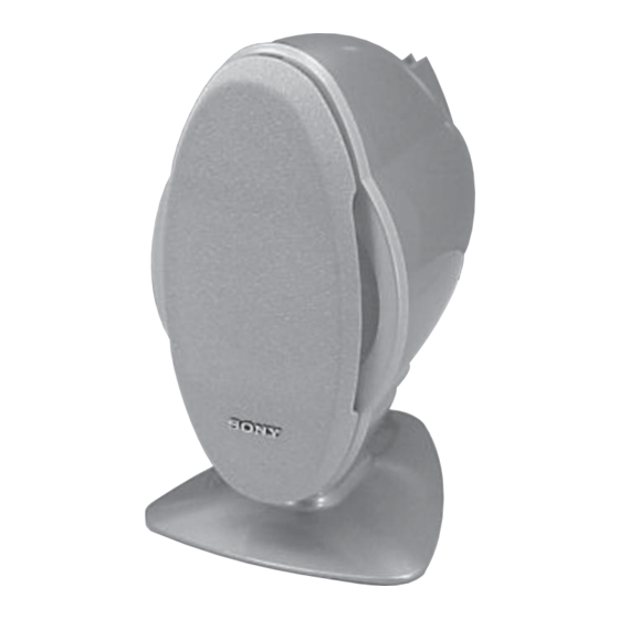
• SA-C7 is the speaker system
in CMT-C7NT.
SAFETY-RELATED COMPONENT WARNING!!
COMPONENTS IDENTIFIED BY MARK 0 OR DOTTED LINE WITH
MARK 0 ON THE SCHEMATIC DIAGRAMS AND IN THE PARTS
LIST ARE CRITICAL TO SAFE OPERATION. REPLACE THESE
COMPONENTS WITH SONY PARTS WHOSE PART NUMBERS
APPEAR AS SHOWN IN THIS MANUAL OR IN SUPPLEMENTS
PUBLISHED BY SONY.
Sony Corporation
9-873-686-01
2002C1600-1
Home Audio Company
© 2002.03
Published by Sony Engineering Corporation
SPECIFICATIONS
Speaker system
Two-way, bass reflex
system
Speaker units
9 cm dia., cone type
woofer
2 cm dia., balance drive
tweeter
Rated impedance
6 ohms
Approx. 149 × 248 ×
Dimensions (w/h/d)
220 mm
Mass
Approx. 1.9 kg net per
speaker
Design and specifications are subject to change without notice.
SA-C7
AEP Model
UK Model
E Model
SPEAKER SYSTEM
Advertisement

Subscribe to Our Youtube Channel
Summary of Contents for Sony SA-C7
- Page 1 SA-C7 SERVICE MANUAL AEP Model UK Model Ver 1.0 2002. 03 E Model • SA-C7 is the speaker system in CMT-C7NT. SPECIFICATIONS Speaker system Two-way, bass reflex system Speaker units 9 cm dia., cone type woofer 2 cm dia., balance drive...
-
Page 2: Service Note
3 If the power voltage is less than +/- 14 V, the speaker relay will not be activated. [Caution when removing the front panel] The special screwdriver (Sony part code No. 7-640-005-55) of star type (six star type) is required to remove the front panel. - Page 3 SA-C7 SECTION 1 DIAGRAMS 1-1. Printed Wiring Board D831,832 – BACK LIGHT FOR SP2 – (11) • Semiconductor Location (AMP Board) Ref. No. Location D821 IC801 Q821 Q822 Q823 Q824 • Semiconductor Location (LED Board) Ref. No. Location D831 D832...
- Page 4 SA-C7 1-2. Schematic Diagram D832 SELS5LED23C-STP15 D831 SELS5LED23C-STP15 D831,832 – BACK LIGHT FOR SP2 – C803 47/50V Note on Schematic Diagram: • All capacitors are in µF unless otherwise noted. p: pF. • A : B+ Line. • B : B– Line.
-
Page 5: Exploded Views
SA-C7 SECTION 2 EXPLODED VIEWS NOTE: • -XX, -X mean standardized parts, so they may • The mechanical parts with no reference number have some differences from the original one. in the exploded views are not supplied. • Items marked “*” are not stocked since they •... -
Page 6: Section 3 Electrical Parts List
SA-C7 SECTION 3 ELECTRICAL PARTS LIST NOTE: • Due to standardization, replacements in the • COILS When indicating parts by reference number, parts list may be different from the parts uH: µH please include the board name. specified in the diagrams or the components •...


Need help?
Do you have a question about the SA-C7 and is the answer not in the manual?
Questions and answers