Table of Contents
Advertisement
Quick Links
Advertisement
Table of Contents

Related Manuals for SMAC VLC-ETC

Summary of Contents for SMAC VLC-ETC
- Page 1 VLC-ETC USER MANUAL Version 1.3...
- Page 2 The contents of this user manual are intended to be as accurate as possible, but may be subject to change without prior notification. SMAC shall not be liable for any damages that may arise as a consequence of the use of information presented in this user manual.
-
Page 3: Table Of Contents
Optional: disabling the STO ................... 12 Software Setup ........................13 2.2.1 VLC configuration ......................13 2.2.2 Connecting VLC-ETC to an EtherCAT network (with a TwinCAT example) ....13 Programming the VLC-ETC ......................16 Servo objects ......................... 16 3.1.1 Acyclic servo objects ...................... 16 3.1.2... -
Page 4: Introduction
Introduction The VLC-ETC is an EtherCAT servo drive that is based on SMAC’s VLC 1-axis integrated controller/driver and an additional layer that provides the EtherCAT connectivity. The VLC part is pre-programmed with system macros to accommodate control and monitoring functionalities of the servo drive. Additional macros can be programmed in the VLC to perform subroutines/functions that can be called from the EtherCAT master. - Page 5 LEDs 2 x 2 LEDs: • EtherCAT LED: Run (green), Error (red) • Servo Drive LED: Power ON (green), Fault (red) • Communication Interface 1x serial/UART (micro USB port): 9600 baud default, selectable between 2400 – 460800 • 2x EtherCAT RJ-45 ports Supply Voltage +24 to +48 VDC •...
-
Page 6: Hardware And Software Setup
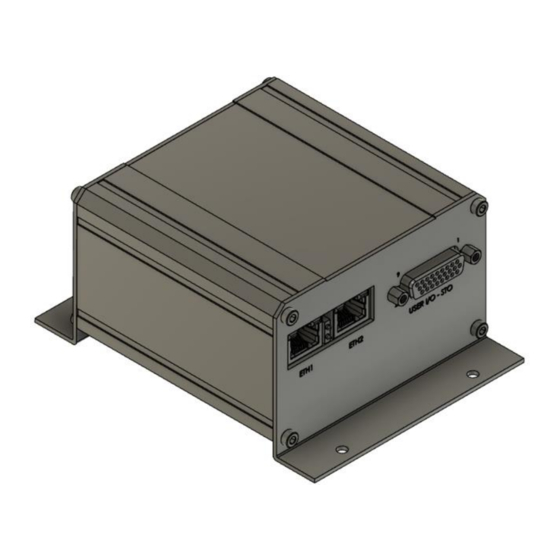
2.1 Hardware 2.1.1 Power/signal/communication connectors Figure 2.1 shows the VLC-ETC in its housing. The front and rear sides’ connectors as well as LED status indicators are depicted in Figures 2.2 and 2.3. Pinout details of the connectors are presented in the following pages of this manual. - Page 7 EtherCAT RUN EtherCAT ERROR Figure 2.2. VLC-ETC front side connectors and LED status indicators. Servo drive power Servo drive fault Figure 2.3. VLC-ETC rear side connectors and LED status indicators.
- Page 8 J1 (EtherCAT input) / J2 (EtherCAT output) RJ-45 Jack. Signal Description Transmit data + Transmit data - Receive data + Receive data - J3 – I/O and STO interface DSUB26 High Density Female Connector. Pin number Signal Description GPI_COM Common terminal for general purpose digital inputs GPO_COM Common terminal for general purpose digital outputs GPI2...
- Page 9 J4 - Power interface 6 pin terminal block header, 5 mm pitch. Pin number Signal Description Power supply return / ground Power supply positive Actuator phase U (positive for single-phase actuators) Actuator phase V (negative for single-phase actuators) Actuator phase W Ground J5 –...
-
Page 10: I/O Electrical Schematics
(such as Tera Term) for configuration and programming purposes, while the EtherCAT communication is being interrupted. To operate the VLC-ETC in EtherCAT mode, make sure to first power cycle the VLC-ETC after disconnecting the micro usb cable from this port. - Page 11 Digital outputs Internal to VLC-ETC +5 V GPO1 (200 mA, 60 VDC tolerant) 620Ω Sinking output from μC output circuitry GPOx 620Ω Sinking output from GPO_COM μC output circuitry Solid-state relays (200 mA, 60 VDC tolerant) Internal to VLC-ETC Opto...
-
Page 12: Optional: Disabling The Sto
Analog input (differential) Internal to VLC-ETC AN_INx+ -10 VDC to 10 VDC 0 – 3.3VDC To μC ADC AN_INx- (12-bit) Differential amplifier Analog output Internal to VLC-ETC From μC DAC (12-bit) AN_OUTx 0 - 10 VDC Non-inverting amplifier 2.1.3 Optional: disabling the STO The two STO inputs (STO1 and STO2, see section 2.1.2) have to be supplied with the specified... -
Page 13: Software Setup
Serial communication can be established between the VLC part and a PC through the micro USB port (J6) of the VLC-ETC. A serial terminal software (with selectable baud rates of up to 460800, such as Tera Term) can be used to configure the VLC for the following purposes: •... - Page 14 ➢ On the left pane of the TwinCAT development environment, right-click on I/O>Devices, select “Add new item”. A window “Insert Device” appears as shown in Figure 2.5. Select EtherCAT Master and click OK. ➢ A window “Device Found At” appears as in Figure 2.6, select the Ethernet adapter that is already installed.
- Page 15 Figure 2.7. VLC-ETC connected to TwinCAT. ➢ Right-click on the newly-added “Device 1 (EtherCAT)” and select scan. The VLC-ETC will appear as shown in Figure 2.7. ➢ To view the various data belonging to VLC_ETC, double-click on Box 1 (VLC_ETC). A list of data will appear as shown in Figure 2.8.
-
Page 16: Programming The Vlc-Etc
Programming the VLC-ETC 3.1 Servo objects Servo objects are parameters and variables that are used to perform control and monitoring of the VLC-ETC. From its update behaviour perspective, there are two servo object types in VLC- ETC: • Acyclic: updated upon request, used for servo configuration purposes. - Page 17 For 3-phase actuators, set the object “Phase and sense setting” (8002;2) to 1 3.1.1.1 Homing parameters Homing parameters (index: 8003) are specific to the VLC-ETC. To perform homing through the manipulation of cyclic objects (further description in the following subsection of this manual), phasing (in case a 3-phase actuator is used) has to be executed successfully beforehand.
-
Page 18: Cyclic Servo Objects
Some of the objects have their VLC equivalence and therefore, further information about them are to be found from the VLC manual. The OUTPUT object value is applied to the VLC-ETC upon a change of its value. Note that GPR’s 101 – 104 are only meaningful when they are used within... - Page 19 Table 3.3. Statusword bits. Description Initialization done. This will be set to 1 after VLC-ETC performs its initialization process upon power-up, indicating that it is ready to be operated. Servo enabled. This will be set to 1 when the servo is enabled by MN command.
- Page 20 Macro call error. Set to 1 if an undefined macro is called. Set to 0 when a new call to a defined macro is performed, or any of the mode of operation is executed. Macro execution. Set to 1 when a macro is being executed. Set to 0 when macro execution is completed.
- Page 21 3.1.2.3 Modes of operation, modes of operation display, setpoint, macro call indicator There are seven servo modes of operation, for which the object “setpoint” has a dependent function, as described in table 3.5. Table 3.5. Modes of operation. Modes Value Description Setpoint function operation...
-
Page 22: Executing Motion Through Servo Objects
3.3 Example: executing homing with TwinCAT under Config mode ➢ Click the icon in the dashed rectangle shown In Figure 3.2 to reload EtherCAT devices and to activate the free-run state of VLC-ETC. Once this is done, the green LED next to the EtherCAT port should stay on. - Page 23 Figure 3.2. Acyclic servo objects list. Figure 3.3. Setting the value of an acyclic servo object. ➢ Under the acyclic servo objects list, there is a list of cyclic object list. Scroll down to find the object “Modes of operation”. Right-click and set its value to 6. ➢...
- Page 24 Figure 3.4. Statusword value with bit 6 set to 1, indicating homing has been successfully completed. Figure 3.5. Setting bit 2 of controlword back to 0.
-
Page 25: Example: Programming A Sequence Of Motions With Twincat Plc Under Run Mode
➢ Another window will appear asking to scan for ‘boxes’. Click OK and EtherCAT terminals will appear and VLC-ETC will be under one of them as shown in Figure 3.7 (provided the VLC-ETC is connected to the EtherCAT junction terminal). - Page 26 Figure 3.7. VLC-ETC under one of the scanned terminals. Figure 3.8. Adding a new PLC project.
- Page 27 ➢ Go to the PLC program editor as shown in the left pane of Figure 3.9. The top rectangle is where the program variables are declared, while the bottom one is where the program logic will be located. In this example, the sequence of motions consists of: phasing – homing – repetitive position move.
- Page 28 Figure 3.9. PLC main program editor in Structured Text language (default). o Enter the following piece of code in the bottom rectangle: CASE State OF 0: // check if the drive is ready to be operated, statusword bit 0 = 1 IF (Statusword.0)=1 THEN State := 1;...
- Page 29 4: // Check if Phasing has been completed IF (Statusword.8) =1 THEN Controlword := 1; Phasing_Error := FALSE; State := 5; END_IF IF (Statusword.9) =1 THEN Controlword := 1; Phasing_Error := TRUE; END_IF 5: // change mode of operation to homing Mode_Op := 6;...
- Page 30 11: // Enter motion parameters Vel := 100000; Acc := 1000000; Setpoint := 4000; Controlword := 2; State := 12; 12: // Check if the movement has started //IF (Statusword.3)=1 THEN IF (Statusword.4)=0 AND (Statusword.3)=1 THEN Controlword := 1; State := 13; END_IF 13: // check if target position has been (almost) reached //IF ABS(Setpoint-Pos_value)<100 THEN...
- Page 31 ➢ Go to the left pane shown in Figure 3.10 and select ‘PlcTask’. Change the Cycle ticks as desired, but not lower than 1 millisecond. ➢ Double-click on ‘Real-Time’ in the left pane of Fig. 19, then select the tab ‘Priorities’. One can change the priority of the tasks in TwinCAT, or to optimize it by clicking on the button that’s shown on the bottom of Figure 3.11.
- Page 32 Otherwise, if the PLC program has never been compiled previously, a window in Figure 3.12 will appear, meaning that the variables defined in the program have to be linked to the cyclic servo objects of the VLC-ETC. ➢ After clicking OK on Figure 3.12, cancel the request to restart TwinCAT in Run Mode as shown in Figure 3.13.
- Page 33 These contain the variables that have been declared in the PLC program. Right-click on each of the variables and select ‘Change link’ and find the corresponding cyclic servo object of the VLC-ETC. ➢ Now, click again on the ‘Activate configuration’, this time, click OK to restart the TwinCAT in Run mode.
- Page 34 Figure 3.16. Executing the PLC program.
-
Page 35: Example: Programming A 2-Axis Linear-Rotary Actuator
3.5 Example: programming a 2-axis linear-rotary actuator VLC-ETC 1 (linear) (to EtherCAT ETH1 Master/PLC) ETH2 VLC-ETC 2 (rotary) ETH1 ETH2 SMAC linear-rotary actuator (e.g. LCR16) MAH-6RED026-03 cable Figure 3.17. Example of a connection schematic for 2 VLC-ETCs (daisy-chained) and a 2-axis linear- rotary actuator. - Page 36 ➢ Double-click on the VLC-ETC and select the “CoE-Online” tab as depicted in Figure 3.19. There is a table with various acyclic objects/configuration parameters such as controller PID settings. Figure 3.19. CoE-Online tab containing acyclic objects. ➢ In the CoE-Online tab, set the following parameters for each VLC-ETC...
- Page 37 Except for homing method, speed, acceleration, position error threshold and homing timeout, the above parameters could be determined from a test previously done actuator for each axis. Alternatively, the acyclic parameters in Table 3.6 can be used for an LCR16-035 actuator. Table 3.6.
- Page 38 ➢ Go to the PLC program editor as shown in the left pane of Figure 3.21. The top rectangle is where the program variables are declared, while the bottom one is where the program logic will be located. In this example, the sequence of motions consists of: phasing – homing – repetitive position move.
- Page 39 // declaration of output variables for axes 1 & 2 Controlword_x1 AT%Q* : UINT; Mode_Op_x1 AT%Q* : UINT; Setpoint_x1 AT%Q* : DINT; Vel_x1 AT%Q* : DINT; Acc_x1 AT%Q* : DINT; Controlword_x2 AT%Q* : UINT; Mode_Op_x2 AT%Q* : UINT; Setpoint_x2 AT%Q* : DINT; Vel_x2 AT%Q* : DINT;...
- Page 40 2: // check if mode of operation has been set accordingly IF ((Mode_Op_Disp_x1 = Mode_Op_x1) AND (Mode_Op_Disp_x2 = Mode_Op_x2)) THEN State := 3; END_IF 3: //start phasing Controlword_x1 := 2; Controlword_x2 := 2; State := 4; 4: // Check if Phasing has been completed successfully IF ((Statusword_x1.8) =1 AND (Statusword_x2.8) =1) THEN Controlword_x1 := 1;...
- Page 41 8: // check if homing has been done successfully IF ((Statusword_x1.6) =1 AND (Statusword_x2.6)=1) THEN Controlword_x1 := 1; Controlword_x2 := 1; Homing_Error_x1 := FALSE; Homing_Error_x2 := FALSE; State := 9; END_IF IF (Statusword_x1.7) = 1 THEN Homing_Error_x1 := TRUE; END_IF IF (Statusword_x2.7) = 1 THEN Homing_Error_x1 := TRUE;...
- Page 42 Vel_x2 := 10000000; Acc_x2 := 10000000; Setpoint_x2 := 0; Controlword_x2 := 2; pos_state := 12; State := 20; 20: // check if motion acknowledgement bit has been set to 1 IF ((Statusword_x1.3)=1 AND (Statusword_x2.3)=1) THEN Controlword_x1 := 1; Controlword_x2 := 1; State := 21;...
- Page 43 Otherwise, if the PLC program has never been compiled previously, a window depicted in Figure 3.23 appears, meaning that the variables defined in the program have to be linked to the cyclic servo objects of the VLC-ETC. Figure 3.22.
- Page 44 VLC-ETC. Variables with ‘_x1’ suffix are to be linked with the VLC-ETC connected to the linear axis, while ‘_x2’ corresponds to the rotary axis.
- Page 45 ➢ On the left-pane of Figure 3.26, select ‘Real-Time’ and go to the ‘Priorities’ tab and click on the ‘Optimize manually’ button highlighted in the below screen. Figure 3.26. ➢ Select ‘I/O Idle Task’ as can be seen in Figure 3.27, change the cycle ticks to 2. Figure 3.27.
- Page 46 ➢ Select ‘Plc Task’ as shown in Figure 3.28, change the cycle ticks to 1. Figure 3.28. ➢ Click on the ‘Activate configuration’ icon highlighted in Figure 3.29, click OK, and accept the request to restart TwinCAT in Run Mode Figure 3.29.
- Page 47 ➢ Click on the ‘Login’ icon highlighted in Figure 3.30, select Yes when there is a request to proceed with download Figure 3.30. ➢ Lastly, click on the button highlighted in Figure 3.31 to execute the program. Figure 3.31.
- Page 48 ➢ In case the previous program does not run: look at the variable ‘State’, which indicates the part where the program gets stuck. This could indicate that the statusword bit corresponding to phasing or homing has not been set to 1, meaning that there is a failure in phasing or homing.
-
Page 49: A Appendix A: Vlc System Macros
A Appendix A: VLC System Macros ; Initialization MD0,EF,BR460800,AL0,AR214,AR224,MJ151 ; default acyclic object parameters MD151,SG0,SI0,SD0,IL0,FV0,FA0,FR0,RI0,SC0,SS2,PH0 MD152,DB0,OO0,SE16383,AL0,AR220,AL5000,AR215,AL5000,AR216,AL0,AR221 MD153,AL200,AR222,AL5000,AR225,AL0,SP0,AL5000,AR200,AL0,AR201 MD154,DA0,AL2047,WW610,AL2147483647,WL612,EP ; initial acyclic objects check MD155,RW516,TR,RW518,TR,RW520,TR,RW522,TR,RW526,TR,RW536,TR,RB550,TR,RB552, TR,RW524,TR,RB1822,TR,RB558,TR,RW560,TR,EP MD156,RW528,TR,RW542,TR,TR220,TR215,TR216,TR221,TR222,TR225,RW604,TR,TR200, TR201,RL592,TR,EP MD157,TR11,TR12,TR13,TR14,TR15,TR16,TR17,TR18,TR19,TR20,TR,EP MD158,TR21,TR22,TR23,TR24,TR25,RW610,TR,RL612,TR,EP ; periodic cyclic objects read MD159,TS,TP,TF,RW548,TR,TR101,TR102,BI0,TR,RC ; Phasing system macros (R200: SQ, R201: EC, R214: phasing status) MD200,AL0,AR214 MD201,MF,EC0,AL32767,AR202,AL16384,AR204,AM@201,IG0,AD65536,MJ202,RA201,AD6 5536,AM@204... - Page 50 ; Torque move system macros (R200: SQ value) MD224,QM0,MN,SQ@200 MD226,QM1,MN,SQ@200 ; Homing system macros (R215: velocity, R216: acceleration, R220: homing method <0-current position, 1-negative mech limit, 2-positive mech limit, 3- negative index, 4- positive index, 5-negative mech limit and index, 6-positive mech limit and index>, R221: home offset, R222: error, R224: homing status, R225: timeout)
Need help?
Do you have a question about the VLC-ETC and is the answer not in the manual?
Questions and answers