
Related Manuals for MDS 4790B


Summary of Contents for MDS 4790B
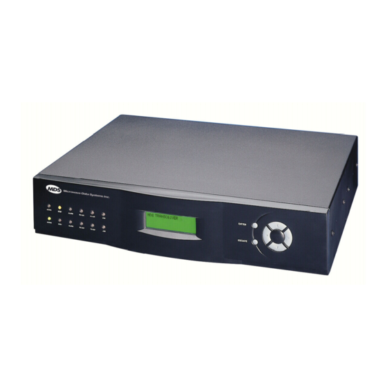
- Page 1 MDS 4790B/9790B 400 MHz/900 MHz Multiple Address System Master Station Radio MDS 05-2765A01, Rev. B OCTOBER 2005...
- Page 2 QUICK START GUIDE 1. Install and connect the antenna system to the radio (Page 11). • Review “Antenna Installation Warning” following the Table of Contents in this manual. • Use a high-quality gain antenna, mounted in the clear. • Use high-quality low-loss feedline. Keep the feedline as short as possible, avoiding sharp bends. 2.
-
Page 3: Table Of Contents
Low Voltage Disconnect Feature............. 18 Battery Reset Switch (SW1) ............18 Antenna Installation ................ 19 Feedline Installation ................ 19 4.5 Interface Wiring Connections ............20 Coaxial Connectors (Type-N)—TX, Antenna, RX ......20 Ground Connection................. 22 MDS 05-2765A01, Rev. B MDS x790B Series I/O Guide... - Page 4 EMP [ON/OFF]................43 HREV ....................44 IF..................... 44 INCF [1–99]..................44 INCP [1–99] ..................44 INIT ....................44 IP..................... 45 KEY....................45 LBC [nnnn] ..................45 LOG [CLR] ..................46 MODEL ................... 46 MDS x790B Series I/O Guide MDS 05-2765A01, Rev. B...
- Page 5 Group 3—Diagnostic Screens ............62 Group 4—Event Log ............... 62 7.0 PROBLEM SOLVING ................77 7.1 Front Panel LEDs ................77 7.2 Chassis-Mounted LEDs ..............78 7.3 Problem Solving Using a Connected PC ........80 MDS 05-2765A01, Rev. B MDS x790B Series I/O Guide...
- Page 6 8.4 Operating Frequency Change Considerations ....... 85 MDS 4790—400 MHz Notch-Type Duplexers......... 85 MDS 9790—Bandpass-Type Duplexers.......... 86 MDS 4790/9790 Simplex Radios—With Antenna Switch Modules. 87 MDS 4790/970—Front End Helical Coil Alignment......87 8.5 Testing and Removing an Internal Duplexer ........87 Testing.....................
- Page 7 3.05 meters (10 feet) of the antenna. Antenna Gain vs. Recommended Safety Distance (MDS 4790B) Station Antenna Gain 0–5 dBi 5–10 dBi...
- Page 8 Warning—400 MHz Distress Beacons In the U.S.A., the 406 to 406.1 MHz band is reserved for use by distress beacons. Since the MDS 4790 Series radio is capable of transmitting in this band, take precautions to prevent the radio from transmitting between 406 to 406.1 MHz.
- Page 9 These systems will reuse or recycle most of the materials found in this equipment in a sound way. Please contact MDS or your supplier for more information on the proper disposal of this equipment.
- Page 10 MDS x790B Series I/O Guide MDS 05-2765A01, Rev. B...
-
Page 11: Introduction
Series transceivers. These “B” model master stations can also be used in systems that include MDS 2100/4100 Series master stations. The MDS 4790B and 9790B are intended to be used as a replacement master station or an expansion unit in an existing system which uses the MDS 2100 or 4100 master station. -
Page 12: Pc-Based Diagnostics
MDS Network-Wide Diagnostics (InSite 6) which uses packetized digital data to convey diagnostic information. The MDS x790B is, however, compatible with InSite 5 diagnostic soft- ware. This software is included on the InSite 6 CD, and includes on-line instructions for its use. -
Page 13: Applications
The following paragraphs describe some basic setups of the MDS x790B master station. In some cases, specific settings or com- mands are necessary for proper operation of the equipment, and these are discussed in the text that follows. Review this information prior to installing the equipment, and refer to Section 6.0 on page 30 for detailed... -
Page 14: Repeater And Polling Remote Operation
4800 and 1200 baud modems and 4-wire analog mode used in the MDS 2100 and 4100 master stations. InSite or MDS 2000 diagnostics can be used from the master station to read data from MDS x710 or MDS x310 series remotes, but the remote Deviation and Frequency Error readouts are not available. - Page 15 1200 and 9600 baud if REPEATER ON the remotes are MDS 2310 or 4310 Series radios. For MDS 4710 and 9710 remotes, the remote’s PTT delay must be set to 5 ms for reliable operation. When operating 4-wire analog Repeaters (...
-
Page 16: Simplex And Switched Carrier Operation
MDS InSite or MDS 2000 diagnostics is not supported in Repeater and Polling Remote modes. The DTMF diagnostics data will not be passed through an MDS x790B repeater, and an MDS x790B Polling Remote cannot receive diagnostic data from a MDS 2100 or 4100 Repeater. -
Page 17: Model Number Codes
This number is subject to many variations depending on what options are installed and where (country) the product is used. Contact MDS is you have questions on the meaning on the code. 2.7 Accessories... -
Page 18: Installation Planning
ALA RM RX ALR TX ALR ACT IVE LINE STB Y ALA RM RX ALR TX ALR LINE EN TE ES CA TO INPUT POWER SOURCE Figure 4. Typical Station Arrangement MDS x790B Series I/O Guide MDS 05-2765A01, Rev. B... -
Page 19: Site Selection
Computer soft- ware is also available for this purpose that can greatly simplify the steps involved in planning a path. MDS 05-2765A01, Rev. B MDS x790B Series I/O Guide... -
Page 20: On-The-Air Test
A Word About Interference Interference is possible in any radio system. However, since the MDS 4790/9790 Series is designed for use in a licensed system, inter- ference is less likely because geographic location and existing operating frequencies are taken into account when allocating frequencies. -
Page 21: Antenna And Feedline Selection
Conversely, a 100 foot (30 meter) length of 1-5/8 inch cable has a loss of 0.52 dB at the same frequency, but its cost is considerably higher than RG-58A/U. MDS 05-2765A01, Rev. B MDS x790B Series I/O Guide... - Page 22 7/8 in. HELIAX 0.13 dB 0.64 dB 1.28 dB 6.40 dB 1-1/4 in. HELIAX 0.10 dB 0.48 dB 0.95 dB 4.75 dB 1-5/8 in. HELIAX 0.08 dB 0.40 dB 0.80 dB 4.00 dB MDS x790B Series I/O Guide MDS 05-2765A01, Rev. B...
-
Page 23: Installation Procedures
Air must be able to pass freely over the heatsink on the rear panel. MDS 05-2765A01, Rev. B MDS x790B Series I/O Guide... -
Page 24: Rack Mounting
Rack Mounting To rack-mount the radio, use the supplied mounting brackets (MDS P/N 82-3184A01) to secure the chassis to the rack cabinet. The brackets can be attached at any of four points on the sides of the enclosure—front,... -
Page 25: Primary Power
15 and 125 Vdc, and 115/230 Vac. The nom- inal input voltage is marked on the module at the rear of the radio or external power supply unit. (See “Technical Specifications” on page 95. for allowable voltage ranges). MDS 05-2765A01, Rev. B MDS x790B Series I/O Guide... -
Page 26: Ac-Powered Units
External DC-power supplies are available as a standard option. Two External Units DC-to-DC power inverters are provided on a open rack shelf. Each inverter is protected from dust and debris by a clear plastic cover. MDS x790B Series I/O Guide MDS 05-2765A01, Rev. B... -
Page 27: Backup Battery
, the radio will continue to operate OFF (0) on battery power until the battery discharges (approximately 1 hour). When shipping or storing the radio, always set the switch to to prevent discharge. BATTERY BACKUP MDS 05-2765A01, Rev. B MDS x790B Series I/O Guide... -
Page 28: Low Voltage Disconnect Feature
12.) Use a pen or other pointed object to press the switch. This will enable the radio to operate until the new battery is discharged or the AC power is restored. MDS x790B Series I/O Guide MDS 05-2765A01, Rev. B... -
Page 29: Antenna Installation
When installing the feedline, take care not to kink, twist or stretch the cable. After installation, fasten the cable securely to the antenna tower or other supporting structure. MDS 05-2765A01, Rev. B MDS x790B Series I/O Guide... -
Page 30: Interface Wiring Connections
If large-diameter, semi-rigid coaxial cable is used for the feedline, insert a short length of 1/4 inch Superflex Cable (MDS P/N 97-1677A28) or other low-loss flexible cable between the radio and the feedline. This flexible interface eliminates tight bends in the feedline and reduces stresses on the feedline and connectors. - Page 31 Contact the factory for filter ordering information. Because the cavity filter must be installed inline, between the master sta- tion receiver and the station antenna, the cabling arrangement in Figure 16 is required. MDS 05-2765A01, Rev. B MDS x790B Series I/O Guide...
-
Page 32: Ground Connection
EIA-574 (9-pin EIA-232) pin functions of the as viewed from the radio’s rear panel. Connection to DIAGNOSTIC PORT J1 can be made with a DB-9 male connector, available from many elec- tronics distributors. MDS x790B Series I/O Guide MDS 05-2765A01, Rev. B... -
Page 33: 4-Wire Audio Connector-J2
Data Connector—J3 The data connector (rear panel of the radio) is the main system data interface It typically connects to the host computer. Refer to Figure 19 Table 4 for pinout details. MDS 05-2765A01, Rev. B MDS x790B Series I/O Guide... - Page 34 RXC—Receive Data Clocking. Provides a clocking signal for synchronizing received data. No Connection 14.0 Vdc Output. Provides a source of regulated voltage at 1.5 amperes for low-power accessories. No Connection No Connection MDS x790B Series I/O Guide MDS 05-2765A01, Rev. B...
-
Page 35: Orderwire-J9
Orderwire—J9 The radio provides for an orderwire channel to facilitate communica- tions between two associated MDS 4790/9790 radios. The jack accepts a standard telephone handset with a carbon microphone and with an RJ-11 connector-equipped cable. See Section on page 27 for further information. -
Page 36: Post Installation Checks
Operation of the radio can be started by simply connecting primary power to the unit and setting the rear panel switch to POWER (Observe the marking on the switch; the setting may be up or down.) MDS x790B Series I/O Guide MDS 05-2765A01, Rev. B... -
Page 37: Normal Indications
LED also lights for the stand-by unit.) Coordinating Activities by Orderwire The orderwire channel can be very useful in coordinating the set-up and testing of two MDS 4790/9790 radios set up in a Polling Remote system configuration. With a telephone handset plugged into the ORDERWIRE jack (J9) on the radio’s rear panel, technicians can talk to each other... -
Page 38: Maximizing Rssi
All other red LEDs are alarm indicators. If lit, they indicate a poten- tial problem in the radio system. Refer to Figure 22 and the text that follows for a detailed explanation of the LED indicators. MDS x790B Series I/O Guide MDS 05-2765A01, Rev. B... -
Page 39: Front Panel Display
At initial power-up, the front panel display shows the start-up screen (Figure 23). After a period of time without any activity, the front panel display darkens. The display can be restored by pressing any of the front panel buttons. MDS 05-2765A01, Rev. B MDS x790B Series I/O Guide... -
Page 40: Local Diagnostics & Control
6.0 LOCAL DIAGNOSTICS & CONTROL Configuration, control and diagnostics of the master station is per- formed by connecting a Windows PC running a terminal program or other MDS diagnostics software to a diagnostic port on the rear of the unit (Figure 24). -
Page 41: Pc Connection For Diagnostic Work
25) between the PC and the radio’s rear panel (Figure 24). DIAGNOSTIC PORT DB-9 MALE CONNECTOR TO RADIO DB-9 FEMALE CONNECTOR TO PC Figure 25. PC Diagnostic Cable (DB-9 to DB-9)— MDS P/N 97-1971A04 MDS 05-2765A01, Rev. B MDS x790B Series I/O Guide... - Page 42 3. Install a terminal emulation program, such as HyperTerminal; or MDS InSite Software (MDS P/N 03-3533A01), if such a program is not already installed. 4. Launch the terminal program or diagnostics software. a. If you are using InSite, follow the instructions given in the pro- gram’s user guide.
-
Page 43: Pc Command Summary Tables
6.2 PC Command Summary Tables MDS radios are pre-configured with operating parameters that enable them to operate in most situations. Should you need to adjust your radio, either for a specific situation or to resolve a problem, this section describes commands for changing radio operating parameters. - Page 44 Set or display the analog audio receive level in to +3] Details Page 51 Details Page 72 Receive Audio Range Receive Pad Enables or disables RX pad. Leave set to OFF. Select Details Page 52 Details Page 73 MDS x790B Series I/O Guide MDS 05-2765A01, Rev. B...
- Page 45 Alarm Status Display Active Radio Status Display current alarm event descriptions Details Page 54 Details Page 75 TEMP Details Page 55 Show Temperature and Display the internal radio temperature Voltages Details Page 76 MDS 05-2765A01, Rev. B MDS x790B Series I/O Guide...
-
Page 46: Command Equivalents For Older Transceivers
(i.e., MDS 2300/4300 Series) that also function with the MDS x790B. Table 10 lists these commands along with cross refer- ences to their equivalents in the MDS x790B command set. In these instances, either the new or old command may be used. 6.4 Detailed Command Descriptions Access Level... -
Page 47: Ak [16-Digit Alphanumeric String]
MDS radio equipment. The key (alphanumeric sting) is unique to each radio chassis and must be purchased from an authorized factory representative. -
Page 48: Alarm
One or more of the radio’s internal voltage regulators is reporting a failure. The radio will not work. 0080 0000 The system has not been calibrated. Factory calibration is required for proper operation of the system. MDS x790B Series I/O Guide MDS 05-2765A01, Rev. B... -
Page 49: Amask [0000 0000-Ffff Ffff]
It is possible to reassign alarm outputs (illustrated in Figure 17 page 23) to a different category, and change which alarm events trigger an automatic switchover in redundant master stations. However, this should be done rarely, if ever. MDS 05-2765A01, Rev. B MDS x790B Series I/O Guide... -
Page 50: Asense [Hi/Lo]
Monitoring & Alarm This command is used to specify whether or not a backup battery is installed and connected to the radio. Set to ON if a backup battery is present. MDS x790B Series I/O Guide MDS 05-2765A01, Rev. B... -
Page 51: Baud [9600 Abc]
DIAGNOSTICS Refer to MODEM [NONE/BELL/4800B/9600B] on page 46 for addi- tional information. The first parameter ( ) is the fixed baud rate for MDS x790B radios. 9600 The second parameter of the command i followed by BAUD s 9600 + Space a 3-character group ( ) indicating how the data is formatted. -
Page 52: Cts [0-255]
CTS line. A timer value of zero means that the CTS line will go high immediately following RTS. Should you experience problems with repeater operation after changing values, contact MDS technical support. DATE [mmm dd yyyy] Event Log Date... -
Page 53: Decp [0-100]
RMST mand. EMP [ON/OFF] TX & RX Emphasis Emphasis screen, page 69 This command is used to enable or disable pre-emphasis and de-emphasis on the analog input and output signals. MDS 05-2765A01, Rev. B MDS x790B Series I/O Guide... -
Page 54: Hrev
This command resets customer-programmable settings back to factory defaults: Table 13. Defaults for User-Configurable Parameters Function Value Alarm Mask—Major (AMASK) 0xFFFF 0000 Alarm Mask—Minor (NMASK) 0x0000 FFFF Alarm Sense—(ASENSE) Active High (Open Circuit) Data—Device Behavior MDS x790B Series I/O Guide MDS 05-2765A01, Rev. B... -
Page 55: Key
Loopback Code This command sets or displays the 4-digit loopback code used during diagnostic testing of the radio. The factory default setting is the last four digits of the radio’s serial number. MDS 05-2765A01, Rev. B MDS x790B Series I/O Guide... -
Page 56: Log [Clr]
—The choice of selects a 4800 bps modem MODEM 4800B 4800B modulation compatible with early MDS radios (i.e., MDS 2100/2300/4300/x710B Series) equipped with a 4800 bps modem. All baud rates up to 4800 are automatically supported as data is received. The command setting is irrelevant. -
Page 57: Nmask [0000 0000-Ffff Ffff]
—The choice of selects a 9600 bps modem MODEM 9600B 9600B modulation compatible with early MDS transceivers (for example: MDS 2100/2300/4300/x710B Series) equipped with a 9600 bps modem. When is selected, the command is 9600B BAUD automatically set to 9600 bps, but it may be configured for either... -
Page 58: Opt
PTT signal or by RTS. The command is not applicable when the radio is keyed by the command. Should you experience problems with repeater operation after changing values, contact MDS. MDS x790B Series I/O Guide MDS 05-2765A01, Rev. B... -
Page 59: Pwr [20-37]
REPEATER the current setting ( = repeater; = not a repeater). Entering the command followed by enables radio operation as a REPEATER repeater; disables operation as a repeater. MDS 05-2765A01, Rev. B MDS x790B Series I/O Guide... -
Page 60: Rmis
Note: For optimum performance with a digital (EIA-232) modem, use the Data Synchronizer Module (MDS P/N 03-1389A02) plugged into the DB-25 connector and set this command to . For DATA REPEATER OFF 4-wire analog operation, the command should be set to... -
Page 61: Rx [Xxx]
This is accomplished using the command, RXMUTE nn where is a time in milliseconds. This causes the receive muting fea- ture to be asserted for nn milliseconds following the end of a transmis- sion. MDS 05-2765A01, Rev. B MDS x790B Series I/O Guide... -
Page 62: Rxpad [On/Off]
—Displays DC input/output voltages. • —Displays the actual (measured) RF power output in dBm. Unlike the command, this command shows the actual level being measured, not the programmed RF power setting. MDS x790B Series I/O Guide MDS 05-2765A01, Rev. B... -
Page 63: Srev
This alarm condition can be read on the Front Panel or by using InSite diag- nostics, but it will not activate the rear panel Alarm Contacts. MDS 05-2765A01, Rev. B MDS x790B Series I/O Guide... -
Page 64: Stat
A/D fault Voltage regulator fault detected Radio not calibrated EEPROM write failure Receiver timeout Transmitter timeout Output power fault Unit address not programmed Data parity error Data framing error Configuration error MDS x790B Series I/O Guide MDS 05-2765A01, Rev. B... -
Page 65: Swc [On/Off]
This command sets the master station receiving mode. If the radio will be listening to an intermittently keyed transmitter such as an MDS x710B or polling remote x790B, set . The only excep- tion is when the radio is being used as a polling remote and is listening to a continuously keyed repeater station. -
Page 66: Tot [On/Off, 1-255]
20 to +3 (inclusive) – TXLEVEL resets the audio level in dBm. Entering the command followed TXLEVEL causes the transmit level to be set automatically. AUTO MDS x790B Series I/O Guide MDS 05-2765A01, Rev. B... -
Page 67: Configuration And Programming Using The Front Panel
6.5 Configuration and Programming using the Front Panel If a PC running MDS diagnostics software is not available to connect to the radio, the front panel display and controls may be used to review and change operating parameters and perform diagnostics. This section explains how to use the front panel controls and screens. -
Page 68: Programming And Control Buttons
• Left/right arrow buttons ( )—The left and right arrow buttons cycle the display through the selected menu’s screens. MDS x790B Series I/O Guide MDS 05-2765A01, Rev. B... - Page 69 North Master 2 Set Time Repeater Mode 11:34:56 PM disabled June 12, 2003 Set Date RX Mute Mode 11:34:56 PM disabled ESCAPE June 12, 2003 Figure 27. Front Panel Screen Flowchart MDS 05-2765A01, Rev. B MDS x790B Series I/O Guide...
-
Page 70: Navigating Through The Front Panel Screens
ENTER 4. Press the down arrow button to display the other access level, USER 5. Press the button to save the change. ENTER MDS x790B Series I/O Guide MDS 05-2765A01, Rev. B... -
Page 71: Use Of Control Buttons In Configuration Mode
This graphic points you to the corresponding PC command entered from a connected PC using the graphic at left. These screens are presented in four major groups: MDS 05-2765A01, Rev. B MDS x790B Series I/O Guide... -
Page 72: Group 1-Startup Screen And Menu Directory
Details Page 74 Details Page 42 Manual Key DKEY Unkey the transmitter (stop transmitting) Details Page 43 Details Page 71 DIAGLEV [OFF, 1, 2, 3] Set or display diagnostic mode. Details Page 43 MDS x790B Series I/O Guide MDS 05-2765A01, Rev. B... - Page 73 “loose” or Details Page 71 Details Page 53 “tight”. Not Available STANDBY [ON/OFF] Set or display whether standby module is present in radio. Details Page 53 MDS 05-2765A01, Rev. B MDS x790B Series I/O Guide...
- Page 74 Details Page 40 Event Log LOG [CLR] Display or clear the event log of the currently Details Page 76, Details Page 46 active transceiver module in the MDS x790 chassis. Clear Logs Details Page 76 Received Signal RSSI, RSSI! Display received signal strength indication...
- Page 75 Display the radio’s model number (includes TX/RX band characteristics) Display the radio’s serial number Not Available Details Page 52 Software Revision Software (Firmware) Display software revision information Revision Level Details Page 76 Details Page 53 MDS 05-2765A01, Rev. B MDS x790B Series I/O Guide...
- Page 76 4 4 4 4 0 0 0 0 0 0 0 0 ..0 0 0 0 0 0 0 0 0 0 0 0 0 0 0 0 0 0 0 0 M M M M H H H H z z z z buttons to select a digit. Then use the up/down arrow buttons to increase or decrease the number. Press ENTER to make the change. TX Operating Frequency command, MDS x790B Series I/O Guide MDS 05-2765A01, Rev. B...
- Page 77 1200 bps Bell 202T modem. All baud rates up to 1200 are automatically supported as data is received. The BAUD command setting is irrelevant. MDS 05-2765A01, Rev. B MDS x790B Series I/O Guide...
- Page 78 MODEM 4800B—The choice of 4800B selects a 4800 bps modem modulation compatible with early MDS radios (i.e., MDS 2100/2300/4300/x710B Series) equipped with a 4800 bps modem. All baud rates up to 4800 are automatically supported as data is received. The BAUD command setting is irrelevant.
- Page 79 Then use the up/down arrow buttons to increase or decrease the digit. Repeat for the other digits if necessary. Press ENTER again to make the change. SCD [0-255] command, Page 52 MDS 05-2765A01, Rev. B MDS x790B Series I/O Guide...
- Page 80 ENTER again to make the change. Note: For optimum performance with a digital modem, use the Data Synchronizer DATA Module (MDS P/N 03-1389A02) plugged into the DB-25 connector and set the Repeater Mode to command to disabled (off). For 4-wire analog operation, Repeater mode should be set to enabled (on).
- Page 81 Settings of 9 and 10 are very tight squelch where a signal levels of –108 to –110 dBm will be needed to break squelch. Longer CTS delays will be needed at the remotes due to the slower opening of the squelch. SQU [1–10] command, Page 53 MDS 05-2765A01, Rev. B MDS x790B Series I/O Guide...
- Page 82 This command sets the master station receiving mode. If the radio will be listening to an intermittently-keyed transmitter such as an MDS x710B remote or an MDS S S S S w w w w i i i i t t t t c c c c h h h h e e e e d d d d C C C C a a a a r r r r r r r r i i i i e e e e r r r r x790B polling remote, set Switched Carrier to enabled.
- Page 83 This screen is used to enable or disable the receive attenuator for the receive audio level through 4-Wire Audio interface. Always set to “disabled” on MDS x790B R R R R e e e e c c c c e e e e i i i i v v v v e e e e P P P P a a a a d d d d radios.
- Page 84 M M M M a a a a y y y y 0 0 0 0 1 1 1 1 1 1 1 1 9 9 9 9 9 9 9 9 9 9 9 9 decrease the day or year, or set the month. Repeat for other characters if necessary. Press ENTER again to make the change. DATE [mmm dd yyyy] command, page 42 MDS x790B Series I/O Guide MDS 05-2765A01, Rev. B...
- Page 85 MDS 05-2765A01, Rev. B MDS x790B Series I/O Guide...
- Page 86 A A A A r r r r e e e e y y y y o o o o u u u u s s s s u u u u r r r r e e e e ? ? ? ? N N N N o o o o MDS x790B Series I/O Guide MDS 05-2765A01, Rev. B...
-
Page 87: Problem Solving
MDS does not recommend component-level repairs in the field. How- ever, the radio’s major assemblies may be replaced without using tools or test equipment. -
Page 88: Chassis-Mounted Leds
To view the chassis LEDs, remove the front panel by grasping it along the bottom edge and pulling straight out (see Figure 31). MDS x790B Series I/O Guide MDS 05-2765A01, Rev. B... - Page 89 MNR ALM Minor Alarm—Indicates a condition which, under most circumstances will not prevent radio operation. This includes out-of-tolerance conditions, baud rate mismatches, etc. The cause should be investigated to prevent system failure. MDS 05-2765A01, Rev. B MDS x790B Series I/O Guide...
-
Page 90: Problem Solving Using A Connected Pc
76). In many cases, the events leading up to a failure can be reviewed to help determine the cause of a problem. Event log messages are also helpful when calling MDS for technical assis- tance. • Major alarms generally indicate a hardware failure or other abnormal condition that will prevent (or hamper) further opera- tion of the radio link. -
Page 91: System Bench Testing Set-Up
26.) An event log is kept within in each of the radio module installed in the MDS x790 chasis.The log of the currently-active (on-line) radio is the one that is displayed on the front panel screen. 7.5 System Bench Testing Set-Up... -
Page 92: Replacing Assemblies
To re-install these modules, make sure that the slides are properly aligned with the guide slots on the chassis, and push straight in. Tighten the thumbscrews to secure the assembly. MDS x790B Series I/O Guide MDS 05-2765A01, Rev. B... -
Page 93: Installation & Removal Of Backup Battery (P/N 28-1575Axx)
3. Place the battery in the chassis in the area provided (see Figure and secure the battery clamp over the battery. The battery should be a minimum rating of 4.5 A/H. MDS 05-2765A01, Rev. B MDS x790B Series I/O Guide... -
Page 94: Front Panel
(Figure 36). You will also need to disconnect the modular cable from the back of the panel. Reverse these steps to re-install the front panel on the chassis. MDS x790B Series I/O Guide MDS 05-2765A01, Rev. B... -
Page 95: Operating Frequency Change Considerations
The duplexers shown in Figure 37 can be aligned in the field by experienced technicians using high-quality test equip- ment. For assistance, please consult MDS Technical Support for addi- tional details about tuning. MDS 05-2765A01, Rev. B MDS x790B Series I/O Guide... -
Page 96: Mds 9790-Bandpass-Type Duplexers
500 kHz without undesired results. Since this type of duplexer cannot be re-aligned in the field, we recommend contacting the MDS Technical Support Department if you suspect a duplexer problem or need one for a different frequency. -
Page 97: Mds 4790/9790 Simplex Radios-With Antenna Switch Modules
Signifi- cant degradation in receive bit-error rate (BER) is likely if the coils are not aligned properly. For assistance, please consult MDS Technical Support for additional details about tuning procedure. 8.5 Testing and Removing an Internal Duplexer... -
Page 98: Removing The Internal Duplexer
While the physical appearance of the duplexer may vary slightly, its operation and removal remain the same. 2. Remove the four screws that mount the duplexer to the chassis as shown in Figure MDS x790B Series I/O Guide MDS 05-2765A01, Rev. B... -
Page 99: Testing And Removing The Antenna Switch Module
1. Measure the RF power out of the antenna jack. If the power registers approximately +37dBm (5 watts), the antenna switch is functioning correctly. (See see “dBm-Volts-watts Conversion Chart” on page 101.) MDS 05-2765A01, Rev. B MDS x790B Series I/O Guide... -
Page 100: Removing The Antenna Switch
1. Remove the four screws that mount the antenna switch module to the chassis as shown in Figure 42 on page 2. Disconnect the cables from the switch module and lift the module out of the chassis. MDS x790B Series I/O Guide MDS 05-2765A01, Rev. B... -
Page 101: Cooling Fan Maintenance
Figure 42. Antenna Switch Module Removal 8.7 Cooling Fan Maintenance The MDS 4790/9790 Series uses cooling fans to cool the main trans- ceiver boards. To ensure that the fans operate correctly, inspect them on a regular basis and keep them clear of dust (Figure 43). -
Page 102: Radio Software Upgrades
Contact MDS Technical Support for details. Finally, if you have an InSite CD from MDS, it also will have radio code on it, but it may not be the latest ver- sion. -
Page 103: Downloading New Code-Procedure
Terminal Mode and repeat the download procedure. 10.0 DIAGNOSTICS & CONTROLOF REMOTE TRANSCEIVERS The MDS x790B Series radio modems support most of the DTMF com- mands used for remote diagnostics and control of MDS transceivers introduced since 1990, but not the original MDS 1000. These products include the MDS 2310/4310 and MDS 1000µ... -
Page 104: Diagnostics Levels
NOTE: Local diagnostic monitoring of the MDS x790B master station is not supported with InSite 5 and the MDS 2000 software. In addition, remote radio Deviation and Frequency Error read- outs are unavailable. The InSite 5 software package is included on the InSite 6 CD-ROM. -
Page 105: Technical Reference
437 mm (17.2 in) wide —includes duplexer and power supply Weight 9 kg (19.8 lbs.) max Frequency Range: MDS 4790: 330 to 512 MHz MDS 9790: 800 o 960 MHz Reprogrammable within smaller bands; duplexer and helical filters may require retuning. TX/RX Split:... - Page 106 24 Vdc 700 mA 2.0 A 48 Vdc 300 mA 1.0 A Redundant 115 Vac 400 mA 1.0 A 24 Vdc 1.2 A 2.5 A 48 Vdc 600 mA 1.2 A MDS x790B Series I/O Guide MDS 05-2765A01, Rev. B...
-
Page 107: Rf Propagation Planning
95% at 40 C, non-condensing Shock and Vibration MIL-810E shipping APPROVALS CE Mark, I/C FCC ID (MDS 9790B): E5MDS9790 (MDS 4790B): E5MD4790 FCC Emission Designator: (MDS 4790B/9790B): 11K2F1D 11.2 RF Propagation Planning Establishing a reliable point-to-point radio link requires system plan- ning and design. -
Page 108: Earth Curvature
15 meters above flat terrain will have a radio horizon approximately 15 kilometers away, well beyond the visual horizon. MDS x790B Series I/O Guide MDS 05-2765A01, Rev. B... -
Page 109: Fade Margins
11.3 Formulas for System Planning The following standard formulas are provided for assistance in deter- mining system installation parameters. Free Space Path Loss 92.4 α where: = free space loss in dB α MDS 05-2765A01, Rev. B MDS x790B Series I/O Guide... -
Page 110: Fresnel Zone Boundary
• 0.25 is used for temperate or northern areas • 0.125 is used for a very dry climate ƒ = frequency in GHz d = path length in km F = fade margin in dB MDS x790B Series I/O Guide MDS 05-2765A01, Rev. B... -
Page 111: Dbm-Volts-Watts Conversion Chart
2.85 10.0 -136 10mW -137 2.25 .1µW -138 6.4mW .001nW -139 .500 -140 .01ƒW .445 5.75 .400 3.2mW .355 2.5mW 1.25 .320 2.0mW 1.18 .280 1.6mW 1.00 3.51 .252 1.25mW 0.90 MDS 05-2765A01, Rev. B MDS x790B Series I/O Guide... -
Page 112: Data Synchronizer Module
A.1 Introduction This optional assembly is available to improve bit-error rates of an MDS 4790B/9790B master station serving as a repeater or polling remote which, is in a system configured for 4800 bps operation. This kit includes the Data Synchronizer assembly (03-1389A01) is a PCB in a... - Page 113 A word includes the start bit, data bits, stop bit and parity bit. Table A-1.Word Switch Settings for Data Synchronizer Board WORD LENGTH SWITCH SW1-1 10 Bits Closed 11 Bits OPEN MDS 05-2765A01, Rev. B MDS x790B Series I/O Guide...
- Page 114 The switch settings are outlined in Table A-2 below. Table A-2. Data Synchronizer Baud Rate Switch Settings DATA RATE SW1-2 SW1-3 SW1-4 150 bps 300 bps 600 bps 1200 bps 2400 bps 4800 bps 9600 bps MDS x790B Series I/O Guide MDS 05-2765A01, Rev. B...
- Page 115 60 percent of the first Fresnel zone should be free of obstructions in a well-designed system. (Additional considerations are also required when planning an RF path. A detailed discus- sion of the subject is presented on page 97 of this guide.) MDS 05-2765A01, Rev. B MDS x790B Series I/O Guide...
- Page 116 SWR—Standing Wave Ratio. A parameter related to the ratio between forward transmitter power and the reflected power from the antenna system. As a general guideline, reflected power should not exceed 10% of the forward power (ª 2:1 SWR). MDS x790B Series I/O Guide MDS 05-2765A01, Rev. B...
- Page 117 MODEL (display radio model number) 46 Baud Rate/Format screen 68 NMASK (classify minor alarm events). See also AMASK Bench test setup 81 command 47 illustrated 81 OPT! (list installed radio options) 48 MDS 05-2765A01, Rev. B MDS x790B Series I/O Guide...
- Page 118 (Manual Key screen) 71 active transceiver board (RADIO command) 49 transmitter state (Transmitter Status screen) 75 active transceiver board (Radio Selection screen) 75 Display Contrast screen 73 active transceiver board’s serial number (Serial Number MDS x790B Series I/O Guide MDS 05-2765A01, Rev. B...
- Page 119 83 screen) 70 MAS network 4 range 95 MDS x790B master station 2 receiver stability 96 mounting dimensions and bracket details 14 set/display receive (Receive Frequency screen) 67 PC connected to the master station 31...
- Page 120 36 illustrated 79 connected to the master station, illustrated 31 use in problem solving 78 connecting to the radio for diagnostics and control 31 LEDs, front panel 28 MDS x790B Series I/O Guide MDS 05-2765A01, Rev. B...
- Page 121 Clear-to-Send Delay 69 key features 6 configuration 66–74 model number codes 7 configuration, listed 62 removing antenna switch module 89 Continuous Keying 71 removing internal duplexer 85, 89 diagnostic, listed 62 MDS 05-2765A01, Rev. B MDS x790B Series I/O Guide...
- Page 122 (OWM command) 48 feedline loss chart 12 owner message (Set Owner Message screen) 74 hexadecimal values for major alarm conditions 38 owner name (OWN command) 48 hexadecimal values for minor alarm conditions 39 MDS x790B Series I/O Guide MDS 05-2765A01, Rev. B...
- Page 123 61 Volts, conversion to dBm or watts, table 101 Watts conversion to dBm or volts, table 101 vs. dBm, table 67 Windows PC. See PC 30 Wiring interface, connections 20 MDS 05-2765A01, Rev. B MDS x790B Series I/O Guide...
- Page 124 MDS x790B Series I/O Guide MDS 05-2765A01, Rev. B...
- Page 125 IN CASE OF DIFFICULTY... MDS products are designed for long life and trouble-free operation. However, this equipment, as with all electronic equipment, may have an occasional component failure. The following infor- mation will assist you in the event that servicing becomes necessary.
- Page 126 Microwave Data Systems Inc. 175 Science Parkway Rochester, NY 14620 General Business: +1 585 242-9600 FAX: +1 585 242-9620 Web: www.microwavedata.com A product of Microwave Data Systems Inc.
Need help?
Do you have a question about the 4790B and is the answer not in the manual?
Questions and answers