
Subscribe to Our Youtube Channel
Related Manuals for MDS 4790 Series


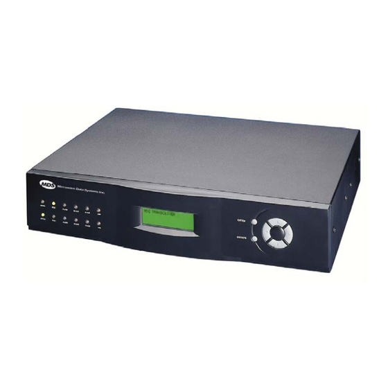
Summary of Contents for MDS 4790 Series
- Page 1 MDS 4790/9790 Series (Including MDS 4790A/C/E/S, MDS 9790A) 400 MHz/900 MHz Multiple Address System Master Station Radio MDS 05-3438A01, Rev. E AUGUST 2005...
- Page 2 QUICK START GUIDE 1. Install and connect the antenna system to the radio (page 8). • Use an appropriate antenna aimed at the associated station. • Use low-loss feedline suited for 400/900 MHz. Keep the feedline as short as possible. 2.
-
Page 3: Table Of Contents
4.6 Interface Wiring Connections ............17 TX, Antenna and RX Coaxial Connectors (Type-N)......18 Ground Connection................. 20 Diagnostics Connector—J1 ............21 4-Wire Audio Connector—J2 ............21 Data Interface Connector—J3 ............22 MDS 05-3438A01, Rev. E MDS 4790/9790 Series™ I/O Guide... - Page 4 NMASK [0000 0000–FFFF FFFF]........... 45 OPT....................46 OWM [xxxxx]................... 46 OWN [xxxxx] ................... 46 PTT [0-255] ..................47 PWR [20–37]................... 47 RADIO [AUTO/A/B] ................. 47 REPEATER [ON/OFF] ..............48 RSSI, RSSI! ..................48 MDS 4790/9790 Series™ I/O Guide MDS 05-3438A01, Rev. E...
- Page 5 (P/N 28-1575Axx) ................... 83 8.3 Front Panel ..................84 8.4 Operating Frequency Change Considerations ....... 85 MDS 4790—400 MHz Notch-Type Duplexers......... 86 MDS 9790—Bandpass-Type Duplexers.......... 86 MDS 4790/9790 Simplex Radios—With Antenna Switch Modules. 87 MDS 05-3438A01, Rev. E MDS 4790/9790 Series™ I/O Guide...
- Page 6 MDS 4790/970—Front End Helical Coil Alignment......87 8.5 Testing and Removing an Internal Duplexer ........87 Testing..................... 87 Removing the Internal Duplexer............88 8.6 Testing and Removing the Antenna Switch Module ....... 89 Testing..................... 89 Removing the Antenna Switch............90 8.7 Cooling Fan Maintenance .............
- Page 7 Warning—400 MHz Distress Beacons In the U.S.A., the 406 to 406.1 MHz band is reserved for use by distress beacons. Since the MDS 4790 Series radio is capable of transmitting in this band, take precautions to prevent the radio from transmitting between 406 to 406.1 MHz.
- Page 8 These systems will reuse or recycle most of the materials found in this equipment in a sound way. Please contact MDS or your supplier for more information on the proper disposal of this equipment.
-
Page 9: Introduction
1.0 INTRODUCTION This guide presents installation and operating instructions for the MDS 4790 and MDS 9790 Series master station. It begins with an overall description of radio features and is followed by the steps required to install the unit and place it into normal operation. -
Page 10: Network-Wide Diagnostics
• Certain messages can be broadcast to all radios in the system simultaneously. The MDS 4790/9790 Series master station can be used to poll remote radios in its radio system for diagnostic data. For more information on the implementation of network-wide diagnostics, see the MDS Network Handbook (P/N 05-3467A01). -
Page 11: Applications
Basic MAS Master Station Operation Figure 2 shows a typical point-to-multipoint system using an MDS 4790/9790 Series master station. This is a basic system consisting of a central master station and several associated remote units. REMOTE RADIO SWC OFF... -
Page 12: Features
2.4 Features Reliability is a hallmark of the MDS 4790/9790 design. The radio employs a one-piece transceiver board which minimizes RF losses and eliminates the need for inter-board cabling. This also allows easy plug-in replacement should servicing become necessary. -
Page 13: Accessories
24 MHz split. (MDS 9790x only) Redundant Radio Adds an additional transceiver board and Consult Fac- Upgrade Kit power supply to a single-radio chassis. tory Operating frequency must be specified when ordering. MDS 05-3438A01, Rev. E MDS 4790/9790 Series I/O Guide... -
Page 14: Model Number Codes
ALA RM RX ALR TX ALR ACT IVE LINE STB Y ALA RM RX ALR TX ALR LINE EN TE ES CA TO INPUT POWER SOURCE Figure 4. Typical Station Arrangement MDS 4790/9790 Series I/O Guide MDS 05-3438A01, Rev. E... -
Page 15: Site Selection
This not only verifies the path study results, but allows you to see firsthand the factors involved at each installation site. MDS 05-3438A01, Rev. E MDS 4790/9790 Series I/O Guide... -
Page 16: A Word About Interference
A Word About Interference Interference is possible in any radio system. However, since the MDS 4790/9790 Series is designed for use in a licensed system, inter- ference is less likely because geographic location and existing operating frequencies are taken into account when allocating frequencies. -
Page 17: Feedline Selection
3 dB. Remember that for each 3 dB of feedline loss, half the transmitter power is lost, and twice the receive signal power is needed to produce the same signal-to-noise ratio. MDS 05-3438A01, Rev. E MDS 4790/9790 Series I/O Guide... -
Page 18: Installation Procedures
Accessories and spare parts kits, if any, are wrapped separately. Inspect all items for signs of damage. Save all packing materials in case you need to ship the radio in the future. MDS 4790/9790 Series I/O Guide MDS 05-3438A01, Rev. E... -
Page 19: Mounting The Radio
Rack Mounting To rack-mount the radio, use the supplied mounting brackets (MDS P/N 82-3184A01) to secure the chassis to the rack cabinet. The brackets can be attached at any of four points on the sides of the enclo- sure—front, back, middle facing front, and middle facing back (see Figure 7). -
Page 20: Remote Front Panel Mounting-Optional Configuration
—Optional Configuration If desired, the front panel can be detached from the radio and mounted separately to the rack cabinet. This optional kit, MDS P/N 03-3228A01, is intended for rack-mount installations where all connections and con- trol must be performed from the rear of the radio. The Auxiliary Mounting Plate (P/N 82-3189A01) is included in the kit. -
Page 21: Primary Power
Non-redundant units will have only one internal or external power supply. The 15 Vdc models have a interface panel and switch on the chassis, but no internal supply. MDS 05-3438A01, Rev. E MDS 4790/9790 Series I/O Guide... -
Page 22: Ac-Powered Units
DC-to-DC power inverters are provided on a open rack shelf. Each inverter is protected from dust and debris by a clear plastic cover. Invisible place holder Figure 10. Typical Rack-Mounted External DC Power Supply (with dual supplies) MDS 4790/9790 Series I/O Guide MDS 05-3438A01, Rev. E... -
Page 23: Backup Battery
DAMAGE 1 hour). When shipping or storing the radio, always set the switch to to prevent discharge. BATTERY BACKUP Invisible place holder Figure 11. Battery Backup Switch Location (Front Panel Removed) MDS 05-3438A01, Rev. E MDS 4790/9790 Series I/O Guide... -
Page 24: Low-Voltage Disconnect Feature
The antenna manufacturer’s installation instructions should be followed for proper operation of the antenna. Using the proper mounting hard- ware and bracket ensures a secure mounting arrangement with no pat- tern distortion or detuning of the antenna. MDS 4790/9790 Series I/O Guide MDS 05-3438A01, Rev. E... -
Page 25: Feedline Installation
If large-diameter, semi-rigid coaxial cable is used for the feedline, insert a short length of 1/4 inch Superflex Cable (MDS P/N 97-1677A28) or other low-loss flexible cable between the radio and the feedline. This flexible interface eliminates tight bends in the feedline and reduces stresses on the feedline and connectors. -
Page 26: Tx, Antenna And Rx Coaxial Connectors (Type-N)
The radio’s ports are the only connectors present, and they connect to the duplexer as shown in Figure 15. Contact the factory for duplexer ordering information. MDS 4790/9790 Series I/O Guide MDS 05-3438A01, Rev. E... - Page 27 (to the duplexer), and the left connector acts as the receive input (from the duplexer). Figure 18 shows the required cable connections between the radio and an external duplexer (and cavity filter, if required). MDS 05-3438A01, Rev. E MDS 4790/9790 Series I/O Guide...
-
Page 28: Ground Connection
Do not overlook providing a good ground connection for the equipment attached to the to prevent damage. DATA PORT Finally, use lightning protectors where the antenna transmission lines enter the building; bond them to the tower ground, if it is nearby. MDS 4790/9790 Series I/O Guide MDS 05-3438A01, Rev. E... -
Page 29: Diagnostics Connector-J1
Connecting pins 5 and 6 together keys the radio. TRANSMIT AUDIO RECEIVE AUDIO 600 OHM 600 OHM EXTERNAL KEYLINE (GROUND TO KEY RADIO) Figure 20. 4-Wire Audio Connector, J2 MDS 05-3438A01, Rev. E MDS 4790/9790 Series I/O Guide... -
Page 30: Data Interface Connector-J3
Receive Audio Monitoring Connection (used for diagnostics). Drives high-impedance load. No Connection No Connection No Connection Do not connect—Reserved for future use. No Connection Do not connect—Reserved for future use. No Connection MDS 4790/9790 Series I/O Guide MDS 05-3438A01, Rev. E... -
Page 31: Orderwire Connector-J9
No Connection Orderwire Connector—J9 The radio provides for an orderwire channel to facilitate communica- tions between two associated MDS 4790/9790 radios. The jack accepts a standard telephone handset with a carbon microphone and with an RJ-11 connector-equipped cable. See Section , Coordinating Activities by Orderwire, beginning on Page 25 for further information. -
Page 32: Post Installation Checks
Since the master station almost always uses an omni-directional antenna, maximizing signal strength is done at the remote sites where directional antennas are typically used. An RSSI stronger than -90 dBm is desirable. MDS 4790/9790 Series I/O Guide MDS 05-3438A01, Rev. E... -
Page 33: Coordinating Activities By Orderwire
Coordinating Activities by Orderwire The orderwire channel can be very useful in coordinating the set-up and testing of two MDS 4790/9790 radios set up in a Polling Remote system configuration. With a telephone handset plugged into the ORDERWIRE jack (J9) on the radio’s rear panel, technicians can talk to each other freely by merely speaking into the handset. -
Page 34: Led Indicators
LED indicators. Invisible place holder ACTIVE STBY ALARM RX ALR TX ALR I/O ALR ACTIVE STBY ALARM RX ALR TX ALR I/O ALR Figure 24. LED Indicators MDS 4790/9790 Series I/O Guide MDS 05-3438A01, Rev. E... -
Page 35: Front Panel Display
Other screens, and the use of the control buttons, are described in Section 6.5, Screen Descriptions, beginning on Page MDS 05-3438A01, Rev. E MDS 4790/9790 Series I/O Guide... -
Page 36: Diagnostics And Control
6.0 DIAGNOSTICS AND CONTROL Configuration, control and diagnostics of the master station is per- formed by connecting a Windows PC running a terminal program or other MDS diagnostics software to a diagnostic port on the rear of the unit (Figure 26). - Page 37 Figure 27. PC Diagnostic Cable (DB-9 to DB-9)— MDS P/N 97-1971A04 3. Install a terminal emulation program, such as HyperTerminal™; or MDS InSite™ software (MDS P/N 03-3533A01), if such a program is not already installed. 4. Launch the terminal program or diagnostics software.
-
Page 38: Pc Command Summaries
You may leave the diagnostics software and PC running, or you may exit from the diagnostics software, power-down the PC, and disconnect the PC from the radio. If you have more than one MDS 4790/9790 master station located at a Connecting Multiple Masters at One Site single site, it is possible to connect all of them to one EIA/RS-232 com- puter connection for local diagnostics and control. -
Page 39: Commands And Command Parameters
• “mm,” “dd,” and “yyyy” stand for month, day and year, respec- tively. (The number of characters used for month and year may vary.) • “hh,” “mm,” and “ss” stand for hours, minutes and seconds, respectively. MDS 05-3438A01, Rev. E MDS 4790/9790 Series I/O Guide... -
Page 40: Baud Rate/Format
Enable or disable repeater mode Details, page 48 Details, page 67 RXMUTE RX Mute Mode Set or display RX (receive) Muting status [ON/OFF/Time in msec] Details, page 68 Details, page 49 MDS 4790/9790 Series I/O Guide MDS 05-3438A01, Rev. E... -
Page 41: Active Radio Status
DIAG Details, page 41 and set the baud rate at the RJ-11 port. DTYPE None Set up a radio as a root, node, gate, or peer [NODE/ROOT/GATE/PE radio. Details, page 42 MDS 05-3438A01, Rev. E MDS 4790/9790 Series I/O Guide... -
Page 42: Manual Key
Disable the transmitter Details, page 41 Details, page 68 MADDR [NONE, 1–255] Multi-Drop Address Unit address for use with MDS’ InSite NMS Details, page 44 (MADDR) software where multiple master stations are Details, page 68 connected together at one location. -
Page 43: Detailed Command Descriptions
The second line is a hexa- decimal numeric code representing the system alarm state. Examples of responses are: NO ALARMS PRESENT CODE: 0000 0000 MINOR ALARMS PRESENT CODE: xxxx xxxx MAJOR ALARMS PRESENT CODE: xxxx xxxx MDS 05-3438A01, Rev. E MDS 4790/9790 Series I/O Guide... - Page 44 Standby radio hardware not installed or available. 0000 0040 The 10-Volt power regulator output is out of tolerance. If the voltage is too far out of tolerance, the radio may not work. MDS 4790/9790 Series I/O Guide MDS 05-3438A01, Rev. E...
-
Page 45: Amask [0000 0000-Ffff Ffff]
‘0’ means that the alarm condition will not cause an alarm output relay to be asserted, and will not cause a radio to switch over. Contact Microwave Data Systems for more information on configuring the alarm response. MDS 05-3438A01, Rev. E MDS 4790/9790 Series I/O Guide... -
Page 46: Asense [Hi/Lo]
110, 300, 1200, 2400, 4800, 9600, 19200, or 38400. The second parameter of the command is a 3-character block spec- BAUD ifying asynchronous data attributes: MDS 4790/9790 Series I/O Guide MDS 05-3438A01, Rev. E... -
Page 47: Buff [On/Off]
) is intended only for applications BUFF ON where the transmitter’s baud rate is greater than or equal to the receiver’s baud rate. Enforcement of this rule is left up to the user. MDS 05-3438A01, Rev. E MDS 4790/9790 Series I/O Guide... -
Page 48: Ckey [On/Off]
The parameter sets the radio to key-on-data mode. The parameter sets the radio to key-on-RTS mode. The default mode is key-on-data. MDS 4790/9790 Series I/O Guide MDS 05-3438A01, Rev. E... -
Page 49: Date [Mmm Dd Yyyy]
RJ-11 DIAG port. followed by the baud rate sets the baud rate (bps) of the RJ-11 DLINK DIAG port. The following baud rates selections are allowed: • 1200 • 2400 MDS 05-3438A01, Rev. E MDS 4790/9790 Series I/O Guide... -
Page 50: Dmgap [Xx]
The default setting is NODE Section 7.2, Performing Network-Wide Radio Diagnostics, begin- ning on Page 80. A complete explanation of remote diagnostics can be found in MDS’ Network-Wide Diagnostics System Handbook. EMP [ON/OFF] TX & RX Emphasis Emphasis screen,... -
Page 51: Hrev
8N1 (8 data bits, no parity, 1 stop bit) Device Behavior Diagnostics Message Gap (DMGAP) 3 ms Key-on-Data Mode (DATAKEY) Modem Analog: None (N/A for MDS 4790E) Digital: MDS x790A: 9600 MDS 4790C: 19200 MDS x790E: 4800 Owner’s Message “Blank”... -
Page 52: Key
COS bus to receive diagnostic information of the master unit itself. The command MADDR will work on MDS x790 master stations with software version 1.7 or later installed. For more details, please see “Connecting Multiple Mas- ters at One Site” on Page MDS 4790/9790 Series I/O Guide MDS 05-3438A01, Rev. -
Page 53: Model
Review the RXLEVEL command on Page 49 and TXLEVEL on Page 55 for guidance on setting appropriate levels. 9600 bps modem speed (used for MDS 4790A/E and 9600— MDS 9790A) 4800 bps modem speed (used for MDS 4790E) 4800— 19200 bps modem speed (used for MDS 4790C) 19200—... -
Page 54: Opt
The entry may contain up to 30 characters and will appear on the default screen of the front panel interface. MDS 4790/9790 Series I/O Guide MDS 05-3438A01, Rev. E... -
Page 55: Ptt [0-255]
5 watts. To read the radio’s actual (measured) power output, use the SHOW PWR command. NOTE: The RF power output of MDS 4790E ETSI certified radios is fixed at 5 watts. No adjustment is possible. RADIO [AUTO/A/B] Active Radio... -
Page 56: Repeater [On/Off]
Remote Terminal Unit This command enables or disables the radio’s internal RTU simulator, which runs with MDS’ proprietary diagnostics software. The internal RTU simulator is an optional feature which may or may not be available on a particular radio; use the... -
Page 57: Rx [Xxx]
This is accomplished using the command, RXMUTE nn where is a time in milliseconds. This causes the receive muting fea- ture to be asserted for nn milliseconds following the end of a transmis- sion. MDS 05-3438A01, Rev. E MDS 4790/9790 Series I/O Guide... -
Page 58: Rxpad [On/Off]
Should you experience problems with repeater operation after changing values, contact MDS. Serial Number Serial Number screen, Page 74 This command displays the radio’s serial number as recorded at the fac- tory. MDS 4790/9790 Series I/O Guide MDS 05-3438A01, Rev. E... -
Page 59: Show [Dc/Pwr/Current/Radio]
S/N Ratio screen, Page 74 These commands display the signal-to-noise ratio in dB. MDS’ defini- tion of signal-to-noise is based upon the signal level following equaliza- tion, for valid data frames only. A valid frame is defined as containing no more than one bit-error, and belonging to a packet addressed for the receiving radio. -
Page 60: Srev
Major alarms are displayed first, then minor ones. The command output displays the event number, major/minor status, and a one- or two-line text message, respectively. If additional alarm events are active, the prompt is displayed. MORE> MDS 4790/9790 Series I/O Guide MDS 05-3438A01, Rev. E... -
Page 61: Temp
Note that the radio is designed to operate in a range from –30 C° to +60 C°, and may fail at temperatures outside this range. This internal reading may be higher than the outside temperature by several degrees. MDS 05-3438A01, Rev. E MDS 4790/9790 Series I/O Guide... -
Page 62: Time [Hh:mm:ss]
TX frequency is set to the center of the radio’s operating band (see Section 2.6, Model Number Codes, beginning on Page 6 for the model’s operating band). MDS 4790/9790 Series I/O Guide MDS 05-3438A01, Rev. E... -
Page 63: Txgain [On/Off]
This command sets or displays the radio’s unit address, which uniquely identifies a single radio within a network in support of a network man- agement system (NMS) program, such as MDS’ InSite™. The default unit address is the last four digits of the radio’s serial number. -
Page 64: Configuration And Programming Using The Front Panel
6.4 Configuration and Programming using the Front Panel If a PC running MDS diagnostics software is not available to connect to the radio, the front panel display and controls may be used to review and change operating parameters and perform diagnostics. This section explains how to use the front panel controls and screens. - Page 65 North Master 2 Set Time Repeater Mode 11:34:56 PM disabled June 12, 2003 Set Date RX Mute Mode 11:34:56 PM disabled ESCAPE June 12, 2003 Figure 28. Front Panel Screen Flowchart MDS 05-3438A01, Rev. E MDS 4790/9790 Series I/O Guide...
-
Page 66: Programming And Control Buttons
(Navigation between individual screens is done using the right or left arrow buttons.) MDS 4790/9790 Series I/O Guide MDS 05-3438A01, Rev. E... -
Page 67: Switching The Front Panel Display To Configuration Mode
In configuration mode, the control buttons have additional functions: • —Starts and ends a change to radio functionality ENTER (enables arrow buttons to be used for selections instead of nav- igation). MDS 05-3438A01, Rev. E MDS 4790/9790 Series I/O Guide... -
Page 68: Making Changes To Radio Functions
These screens are starting points for all programming and viewing activ- ities. Group 2—Configuration Screens (Page The Configuration screens are used to view or define the radio’s oper- ating parameters. Group 3—Diagnostic Screens (Page MDS 4790/9790 Series I/O Guide MDS 05-3438A01, Rev. E... -
Page 69: Group 4-Event Log
Set or display keying behavior (key-on-data or Details, page 69 Details, page 40 key-on-RTS) Multi-Drop Address MADDR [NONE, 1–255] Unit address for use with MDS’ InSite NMS (MADDR) Details, page 44 software where multiple master stations are Details, page 68 connected together at one location. - Page 70 TOT [ON/OFF, 1-255] Set or display the Transmit Timeout duration tion Details page 54 (time to wait before disabling the transmitter Details, page 67 to prevent unnecessary use of the frequency) MDS 4790/9790 Series I/O Guide MDS 05-3438A01, Rev. E...
-
Page 71: Serial Number
Start-up Screen Display the radio name, owner name, owner Details, page 64 message, and any alarms Unit Diagnostic Address UNIT [10000–65000] Displays the radio’s unit address Details, page 55 Details, page 55 MDS 05-3438A01, Rev. E MDS 4790/9790 Series I/O Guide... - Page 72 To change the current frequency, press ENTER, then use the left/right arrow buttons to select a digit. Then use the up/down arrow buttons to increase or decrease the number. Press ENTER to make the change. TX [xxxx] command, Page 54 MDS 4790/9790 Series I/O Guide MDS 05-3438A01, Rev. E...
- Page 73 Press ENTER to make the change. Review the Receive Level parameter on Page 71 and Transmit Gain parameter on Page 71 for guidance on setting appropriate levels. MODEM [NONE/4800/9600/19200/ DEFAULT] command, MDS 05-3438A01, Rev. E MDS 4790/9790 Series I/O Guide...
- Page 74 Then use the up/down arrow buttons to increase or decrease the digit. Repeat for the other digits if necessary. Press ENTER again to make the change. PTT [0-255] command, Page 47 MDS 4790/9790 Series I/O Guide MDS 05-3438A01, Rev. E...
-
Page 75: Soft Carrier De-Key Delay
To change the operating mode, press ENTER, then use the up/down arrow buttons to select ENABLE (repeater mode) or DISABLE (non-repeater mode). Press ENTER again to make the change. REPEATER [ON/OFF] command, Page 48 MDS 05-3438A01, Rev. E MDS 4790/9790 Series I/O Guide... - Page 76 COS bus to receive diagnostic information of the master unit itself. The MADDR command will work on MDS x790 master stations with software version 1.7 or later installed. For more details, please see “Connecting Multiple Masters at One Site”...
- Page 77 The radio’s unit address identifies itself as a unique radio within a network managed by MDS’ InSite™ NMS software or similar program. This address is U U U U n n n n i i i i t t t t A A A A d d d d d d d d r r r r e e e e s s s s s s s s...
- Page 78 Press ENTER again to make the change. Evaluate system performance in the AUTO mode. In most cases, this setting will provide satisfactory performance. If it does not, evaluate the BER at the other settings. MDS 4790/9790 Series I/O Guide MDS 05-3438A01, Rev. E...
- Page 79 To change the selection, press ENTER, then use the left/right arrow buttons to move the bar display to the desired setting. The screen changes dynamically to show the effects of the change. Press ENTER again to set the change. MDS 05-3438A01, Rev. E MDS 4790/9790 Series I/O Guide...
- Page 80 S S S S e e e e t t t t O O O O w w w w n n n n e e e e r r r r M M M M e e e e s s s s s s s s a a a a g g g g e e e e OWM [xxxxx] command, Page 46 MDS 4790/9790 Series I/O Guide MDS 05-3438A01, Rev. E...
- Page 81 - - - - 1 1 1 1 2 2 2 2 0 0 0 0 d d d d B B B B m m m m RSSI, RSSI! command, Page 48 MDS 05-3438A01, Rev. E MDS 4790/9790 Series I/O Guide...
- Page 82 5 5 5 5 A A A A u u u u g g g g 1 1 1 1 9 9 9 9 9 9 9 9 8 8 8 8 MDS 4790/9790 Series I/O Guide MDS 05-3438A01, Rev. E...
-
Page 83: Local & Network-Wide Problem Solving
MDS does not recommend component-level repairs in the field. How- ever, the radio’s major assemblies may be replaced without using tools or test equipment. -
Page 84: Local Problem-Solving
TX ALR Transmit circuitry fault. I/O ALR A data framing or parity error has occurred over the data port. MDS 4790/9790 Series I/O Guide MDS 05-3438A01, Rev. E... -
Page 85: Chassis-Mounted Leds
Figure 33. Front Panel Removal Refer to Figure 34 and the text that follows for an explanation of the LED functions. Invisible place holder Figure 34. Chassis-Mounted LEDs (Front Panel Removed) MDS 05-3438A01, Rev. E MDS 4790/9790 Series I/O Guide... -
Page 86: Problem Solving Using A Connected Pc
75). In many cases, the events leading up to a failure can be reviewed to help determine the cause of a problem. Event log messages are also helpful when calling MDS for technical assis- tance. MDS 4790/9790 Series I/O Guide... -
Page 87: System Bench Testing Set-Up
This test can be performed with any number of remote radios by using a power divider with the appro- priate number of output connections. MDS x710 and x790 radios include an internal RTU simulator. Use the command (see “RTU [ON/OFF/0-80]” on Page 48) to poll remote radios. -
Page 88: Performing Network-Wide Radio Diagnostics
Figure 35. System Bench Test Set-up 7.2 Performing Network-Wide Radio Diagnostics Radios in a network can be remotely polled by connecting a laptop or PC running MDS InSite diagnostics software to any radio in the net- work. Figure 35 shows an example of a setup for performing net- work-wide remote diagnostics. - Page 89 5. Connect same-site radios using a null-modem cable at the radios’ diagnostic ports. 6. Connect a PC on which MDS InSite software is installed to the root radio, or to one of the nodes, at the radio’s diagnostic port. (This PC...
-
Page 90: Replacing Assemblies
To re-install these modules, make sure that the slides are properly aligned with the guide slots on the chassis, and push straight in. Tighten the thumbscrews to secure the assembly. MDS 4790/9790 Series I/O Guide MDS 05-3438A01, Rev. E... -
Page 91: Installation & Removal Of Backup Battery (P/N 28-1575Axx)
3. Place the battery in the chassis in the area provided (see Figure and secure the battery clamp over the battery. The battery should be a minimum rating of 4.5 A/H. MDS 05-3438A01, Rev. E MDS 4790/9790 Series I/O Guide... -
Page 92: Front Panel
(Figure 40). You will also need to disconnect the modular cable from the back of the panel. Reverse these steps to re-install the front panel on the chassis. MDS 4790/9790 Series I/O Guide MDS 05-3438A01, Rev. E... -
Page 93: Operating Frequency Change Considerations
5 MHz will require retuning or the duplexer and/or the receiver’s front-end helical circuits. (See “MDS 4790/970—Front End Helical Coil Alignment” on Page 87) Retuning of these circuits will provide operation with max- imum receiver sensitivity and protection from damage to the radio’s... -
Page 94: Mds 4790-400 Mhz Notch-Type Duplexers
Figure 41 can be aligned in the field by experienced technicians using high-quality test equip- ment. For assistance, please consult MDS Technical Support for addi- tional details about tuning. Figure 41. 400 MHz Notch Duplexer (No adjustment needed for transmit changes up to 100 kHz) -
Page 95: Mds 4790/9790 Simplex Radios-With Antenna Switch Modules
Signifi- cant degradation in receive bit-error rate (BER) is likely if the coils are not aligned properly. For assistance, please consult MDS Technical Support for additional details about tuning procedure. 8.5 Testing and Removing an Internal Duplexer... -
Page 96: Removing The Internal Duplexer
2. Remove the four screws that mount the duplexer to the chassis as shown in Figure 3. Carefully lift the duplexer out of the chassis. MDS 4790/9790 Series I/O Guide MDS 05-3438A01, Rev. E... -
Page 97: Testing And Removing The Antenna Switch Module
If the power registers approximately +37dBm (5 watts), the antenna switch is functioning correctly. (See paragraph 10.4 for dBm-Volts-Watts conversion chart.) If the power registers significantly less than +37dBm, proceed with Step 2. MDS 05-3438A01, Rev. E MDS 4790/9790 Series I/O Guide... -
Page 98: Removing The Antenna Switch
1. Remove the four screws that mount the antenna switch module to the chassis as shown in Figure 2. Disconnect the cables from the switch module and lift the module out of the chassis. Figure 46. Antenna Switch Module Removal MDS 4790/9790 Series I/O Guide MDS 05-3438A01, Rev. E... -
Page 99: Cooling Fan Maintenance
8.7 Cooling Fan Maintenance The MDS 4790/9790 Series uses cooling fans to cool the main trans- ceiver boards. To ensure that the fans operate correctly, inspect them on a regular basis and keep them clear of dust (Figure 47). AIR FLOW... -
Page 100: Preparing For Download
Contact MDS Technical Support for details. Finally, if you have an InSite CD from MDS, it also will have radio code on it, but it may not be the latest ver- sion. -
Page 101: Technical Reference
ETSI-certified radios. Other bands pending. Contact the factory for additional information. TX/RX Split: MDS 4790: Simplex to 132 MHz MDS 9790: Simplex to 160 MHz Tunable Bandwidth: 5 MHz maximum w/o alignment of RX helical filters Frequency Step Size: 6.25 kHz, 5.0 kHz (All models) - Page 102 100 mw to 5 W in 1 dB increments ETSI certified “E” models—5 watts (fixed) Duty Cycle: Continuous Output Impedance: 50 Ohms Bandwidth Compatibility: 12.5 kHz, 25 kHz for MDS 4790C-model Harmonics 2nd harmonic: –73 dBc 3rd harmonic and higher: –67 dBc...
-
Page 103: Rf Propagation Planning
It is helpful to have an understanding of the physical parameters affecting propagation. The following material discusses these factors and will assist you in designing a dependable transmission path for your radio link. MDS 05-3438A01, Rev. E MDS 4790/9790 Series I/O Guide... -
Page 104: Fresnel Zone Clearance
As a matter of practice, 60 percent of the first Fresnel zone must be clear of obstructions (0.6 x F) to allow a clear, unobstructed RF path. Remember, the first Fresnel zone calculation is only one parameter determining path quality. MDS 4790/9790 Series I/O Guide MDS 05-3438A01, Rev. E... -
Page 105: Earth Curvature
In general, mountainous areas have favorable propagation conditions, while trop- ical areas and those near large bodies of water have adverse conditions. MDS 05-3438A01, Rev. E MDS 4790/9790 Series I/O Guide... -
Page 106: Calculating Path Loss
= free-space path loss in dB = receive antenna gain in dBi = receive feedline loss in dB rfl = transmit feedline loss in dB tfl = transmit antenna gain in dBi MDS 4790/9790 Series I/O Guide MDS 05-3438A01, Rev. E... -
Page 107: Probability Of System Fading
• 0.25 is used for temperate or northern areas • 0.125 is used for a very dry climate ƒ = frequency in GHz d = path length in km F = fade margin in dB MDS 05-3438A01, Rev. E MDS 4790/9790 Series I/O Guide... -
Page 108: Dbm-Volts-Watts Conversion Chart
2.85 10.0 -136 10mW -137 2.25 .1µW -138 6.4mW .001nW -139 .500 -140 .01ƒW .445 5.75 .400 3.2mW .355 2.5mW 1.25 .320 2.0mW 1.18 .280 1.6mW 1.00 3.51 .252 1.25mW 0.90 MDS 4790/9790 Series I/O Guide MDS 05-3438A01, Rev. E... - Page 109 DCE device which is designed points (the point at which the power is reduced to connect to a DTE device. 3 dB with respect to the main beam). MDS 05-3438A01, Rev. E MDS 4790A/9790A Installation and Operation Guide...
- Page 110 It is caused by reflections of the transmitted wave and results in distortion at the receiver or weak received signal strength. Network-Wide Diagnostics—An advanced method of controlling and interrogating MDS radios in a radio network. Non-intrusive diagnostics—See Passive mes- saging.
- Page 111 MODEM (set signal type and modulation mode) 45 setting for RJ-11 DIAG port (DLINK command) 41, 80 NMASK (classify minor alarm events). See also AMASK Baud Rate/Format screen 66 command 45 MDS 05-3438A01, Rev. E MDS 4790/9790 Series Installation and Operation Guide...
- Page 112 Diagnostic port screen) 73 cable connecting PC to radio 29 received signal strength (RSSI, RSSI! commands) 48 connecting 21 repeater mode (Repeater Mode screen) 67 J1 pin connections, illustrated 21 MDS 4790/9790 Series Installation and Operation Guide MDS 05-3438A01, Rev. E...
- Page 113 Antenna switch module removal 90 Event Log screen 75 audio connections 21 bench test setup 80 data connector 22 DC power supply 14 Fade margin diagnostics port J1 pin connections 21 MDS 05-3438A01, Rev. E MDS 4790/9790 Series Installation and Operation Guide...
- Page 114 Keying MODEM command (set signal type and modulation mode) 45 activate transmitter (KEY command). See also DKEY Modem screen 65 command 44 Modem, set/display internal speed (Modem screen) 65 MDS 4790/9790 Series Installation and Operation Guide MDS 05-3438A01, Rev. E...
- Page 115 89 using LCD display 78 transceiver boards, about 82 using LED indicators 76 REPEATER command (enable/disable repeater Procedures configuration) 48 assembly replacement 82 Repeater Mode screen 67 MDS 05-3438A01, Rev. E MDS 4790/9790 Series Installation and Operation Guide...
- Page 116 (SCD command) 50 selecting a main menu item 59 soft carrier de-key delay (Soft Carrier De-Key Delay selection arrow 58 screen) 67 Serial Number 74 MDS 4790/9790 Series Installation and Operation Guide MDS 05-3438A01, Rev. E...
- Page 117 PC commands 32 Technical reference 93–100 specifications 93 TEMP command (display internal temperature) 53 Temperature, display internal (TEMP command) 53 Testing. See Bench testing TIME command (set/display time) 54 Timers MDS 05-3438A01, Rev. E MDS 4790/9790 Series Installation and Operation Guide...
- Page 118 ACT IVE STB Y ALA RM RX ALR TX ALR ACT IVE LINE STB Y ALA RM RX ALR TX ALR LINE EN TE ES CA MDS 4790/9790 Series Installation and Operation Guide MDS 05-3438A01, Rev. E...
- Page 119 IN CASE OF DIFFICULTY... MDS products are designed for long life and trouble-free operation. However, this equipment, as with all electronic equipment, may have an occasional component failure. The following informa- tion will assist you in the event that servicing becomes necessary.
- Page 120 Microwave Data Systems Inc. 175 Science Parkway Rochester, NY 14620 General Business: +1 585 242-9600 FAX: +1 585 242-9620 Web: www.microwavedata.com A product of Microwave Data Systems Inc.
Need help?
Do you have a question about the 4790 Series and is the answer not in the manual?
Questions and answers