
Related Manuals for WMT CNC210

Summary of Contents for WMT CNC210
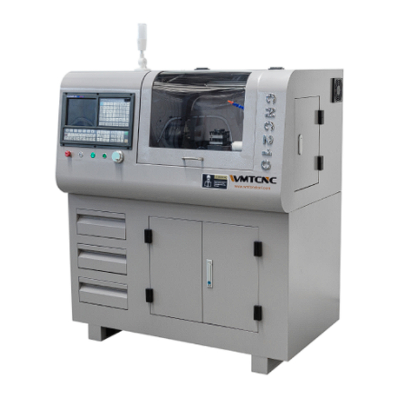
- Page 1 CNC210 Operating Manual CNC lathe Model CNC210 OPERATING MANUAL (Mechanical part) WMT CNC INDUSTRIALCO.,LTD...
-
Page 2: Table Of Contents
CNC210 Operating Manual Contents 1.General Instruction……………………………………………………2 2 Safety guide for operating this machine………………………………3 3.Lifting and Installing………………………………...……..8 4.Technical data………………………………………………………11 5.Machine structure……………………………………………………12 6.Operating instruction and safety protection……………………….…15 7.Inspection and maintenance…………………………………………16... -
Page 3: General Instruction
CNC210 Operating Manual Note:Please read the operation manual carefully before using the machine. 1.General Instruction 1.1 The scope and purpose of this operation manual . This manual is written for the flat bed CNC lathe to guide the user to accurately use the machine which produced by our company , please read it carefully. -
Page 4: Safety Guide For Operating This Machine
CNC210 Operating Manual C.Altitude:1000 meters below D. Radiation: Avoid the change of ambient temperature caused by direct sunlight or other heat radiation E.Installation position should be far away from the vibration source and inflammable and explosive materials, away from the electromagnetic interference area... - Page 5 CNC210 Operating Manual 3.1 The requirement to the operation and maintenance person. The operation who use the machine should be well trained and should be qualified. Before using the machine ,the operation should carefully read the manual operation ,and fully understand what mention in the manual operation.
- Page 6 CNC210 Operating Manual H:you should confirm in advance before you operation the switch,no mistakes,or prone to accidents. Don’t touch the switch at will. 3.3 Requirement before power supply Danger: Cable, coil, wire, electrical components, if there is damage, will produce leakage, causing electric shock accident.
- Page 7 CNC210 Operating Manual C:Please check the protective cover and door and other safety devices are safe, normal work. D:Please check the belt, if not meet the requirements of the specification, please adjust or replace. The belt should be intact without damage.
- Page 8 CNC210 Operating Manual D: Don’t use hands or clothes in contact with rotating work piece and the main spindle. E:In the process of automatic ,please don’t open the guard door of the machine. F:In heavy duty processing, should avoid chip accumulation, because hot chips may cause fire, heat accumulation will cause the thermal deformation of the machine, affect the processing precision.
-
Page 9: Lifting And Installing
CNC210 Operating Manual A:Front and behind protection and cooling protection. B:exceed range limited device(According to the specific configuration) C:Storage stroke limiting device(NC software) 3.12 The work before repair Warning: A: Without permission to do any maintenance work. B:Replacement parts, vulnerable parts should be arranged advanced. - Page 10 CNC210 Operating Manual The machine adopts waterproof package, and the key parts coated with antirust oil, packaging box using the anti vibration and impact measures, can guarantee in ℃to 55℃ temperature range safety transportation and storage. But the packaging box absolutely not allow upside down or tilt more than 50, does not allow violent impact and vibration, so as to avoid damage to the internal device.
- Page 11 CNC210 Operating Manual Attention: The best way to adjust the install position is the forklift. Note: using the circular vibration pad iron (Random) 4.3.2 lifting requirements The machine and the packing box is not recommended for lifting and adjusting the installation position, it is best to use a forklift truck, if not to have to be suspended, please pay attention to the following requirements.
-
Page 12: Technical Data
CNC210 Operating Manual Covers an area including the machine tool itself covers an area of operation (see figure below). 4.4.2 Temporary level adjustment A:Lift or fork the machine, adjusting the pad iron bolts penetrated into the base of the anchor bolt hole. -
Page 13: Machine Structure
CNC210 Operating Manual C:6 months later, we can change the appropriate extension of the inspection period, according to the machine ,until the change is stable to a certain extent, a year can be one to two times the inspection. 5 Structure of machine 5.1 Machine layout... - Page 14 CNC210 Operating Manual 1.main motor 2.Multi wedge belt 3.Z axis feed motor 4.Angular contact bearing 5.Deep groove ball bearing 6. Spindle 7. Angular contact bearing 8.Longitudinal lead screw 9.Deep groove ball bearing, 10, X axis feed motor 11.Synchronous belt 12.Angular contact bearing 2.13.
- Page 15 CNC210 Operating Manual X axis, Z axis feed motion is by two step through the coupling (synchronous belt and synchronous belt wheel) connected with the ball screw nut pair then by the ball screw nut transfer to the carriage or in a small trailer to achieve. Ball screw nut pair has been pre- tight, can achieve high precision gap less transmission 5.2.4 photoelectric encoder drive system...
-
Page 16: Operating Instruction And Safety Protection
CNC210 Operating Manual Lubrication diagram Note: before processing should clean up the rail surface, especially machining of cast iron or to produce debris non-ferrous metal pieces should be often wipe the surface of the guide rail, and to ensure adequate lubrication. -
Page 17: Inspection And Maintenance
CNC210 Operating Manual operator and the environment ,the protective doors with transparent material, we can clearly see the machine’s running situation when in processing. B: The protection of X and Z axis. X, Z axis adopts metal protection, can effectively block cutting fluid and scrap iron . - Page 18 CNC210 Operating Manual 1. Whether there is noise and shake Moving parts 2. Whether the shift is smooth and normal. 1. Whether the switch and the hand shank is Operation panel normal 2. Whether can display the alarm. Safety device Function is normal.
- Page 19 CNC210 Operating Manual A:whether the cooling pump is working properly ,no noise, flow and rated value. B:whether the cooling liquid need to be replaced:when the nozzle out of the water reduction, should check the level of the tank, timely replenishment. If it is too dirty, please timely replacement.
- Page 20 CNC210 Operating Manual Between small carriage and the carriage, carriage and bed ,the sliding surface are used angle plug iron, the plug iron inclination to 1:100. Inclined plane with the surface after distribution scraping, and ensure good contact, when the gap is bigger, you can use the screws at the ends of the gradual adjustment of the position of the plug iron to adjust the size of the gap.
- Page 21 CNC210 Operating Manual Tail sleeve lubricating is not in a good condition. 7.5.10 The runout of the tail sleeve center is too large. A:The tailstock bear a large thrust . B: The gap between tail stock and tail stock sleeve is to large.
- Page 22 CNC210 Operating Manual CNC210-04A-008 spacer CNC210-04-004 Bearing gland GB70-85 Screw M4╳14 GB1387-92 Skeleton oil seal 16╳28╳7 CNC219094A-002 Z axis ball screw 1set GB70-85 Screw M4╳14 CNC210-05A-001 Connection seat GB118-2000 Taper pin 6╳20 GB70-85 Screw M6╳18 CNC210-05-002 Nut seat GB/T276-94 Bearing 6200-2Z P5 GB70-85 Screw M6╳30...
- Page 23 CNC210 Operating Manual Three jaw chuck Φ100 CNC210-02B-001 Spindle GB897-88 Double end studs M8╳30 GB41-2000 Nut M8 GB1096-79 Key 6╳40 GB70-85 Screw M6╳14 CNC210-02B-002 The spindle end cover CNC210-02B-003 Shield ring GB/T292-94 Duplex angular contact bearings in pairs 7008C-DB P4...
- Page 24 CNC210 Operating Manual CNC210-02B-013 synchronous pulley B GB/T88-2000 Allen flat end set screws M5╳8 GB70-85 Screw M6╳16 GB95-85 Flat washer 6 CNC210-02B-014 The encoder seat The encoder ZSP5208 GB70-85 Screw M5╳12 Drawing of carriage assembly Part s list Parts No.
- Page 25 CNC210 Operating Manual CNC210-03A-007 The adjusting screw CNC210-03A-005 Briquetting GB97-2000 Six pyramid end screw M4╳8 GB/T77-2000 Allen flat end set screws M4╳6 CNC210-03A-006 Carriage gib WM180V-02-031 Scraping the crumbs board A CNC210-03A-001 Carriage GB/T276-94 Bearing 619/8-2Z CNC210-03A-003 X axis ball screw seat GB70-85 Screw M6╳25...
- Page 26 CNC210 Operating Manual CNC210-03A-008 X axis motor cover GB70-85 Screw M5╳10 Feed motor GB70-85 Screw M4╳14 GB/T78-2000 Six pyramid end screw M5╳5 CNC210-03-004 Scraping the crumbs board A Synchronous belt 60XL037 GB70-85 Screw M5╳16 CNC210-03-008 The motor mounting plate GB70-85 Screw M5╳20...
- Page 27 CNC210 Operating Manual WM180V-05A-005 Tailstock end cover WM180V-05A-009 Calibration loop WM180V-05A-004 Hand wheel WM180V-05A-019 JB/T7270.1-94 Handle B-M5╳40 WM180V-05A-010 Leaf spring GB1096-79 Key 4╳12 GB1155-79 Oil cup 6 GB/T79-2000 Screw M5╳6 WM180V-05A-006 Lock pressing sleeve WM180V-05A-015 Lock screw JB/T7270.1-94 Handle HY8310.1 B-M6╳50...
Need help?
Do you have a question about the CNC210 and is the answer not in the manual?
Questions and answers