Advertisement
Quick Links
Creative Lighting made for Control4 Vibrant
DALI/DMX Gateway Installation Guide
Supported models
• CRE-EDIDIO-10-1D - Digital Lighting Gateway, DALI 1 bus
• CRE-EDIDIO-10-1X - Digital Lighting Gateway, DMX 1 universe
• CRE-EDIDIO-10-2D - Digital Lighting Gateway, DALI 2 buses
• CRE-EDIDIO-10-2X - Digital Lighting Gateway, DMX 2 universes
• CRE-EDIDIO-10-1D-1X - Digital Lighting Gateway, 1 Dali bus, 1 DMX
universe
Accessories
• CRE-SPLTR-V2-LTNG: DMX Splitter Repeater with added protection
from lightning
• CRE-UBI-V2-PWR: DALI Power 21V DC (250 mA)
• HDR-60-24: 24V DC, 60W power supply
• CRE-ADDICT: ADDICT V3 for DALI, DMX commissioning, with RDM
support and WiFi
Introduction
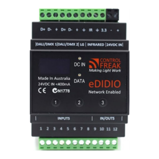
The eDIDIO S10 gateway is a modular, network-enabled, DIN rail
mounted, DALI and DMX lighting controller. It supports up to two lines
of control via DALI, DMX, or both. This model is specially configured
to work with Control4.
Features
Modular control: Modular hardware allows for any combination of
up to two (total) DALI and or DMX512-A outputs while still maintaining
proper DMX512-A signal conditioning and DALI separation.
Custom Control4 protocol: The eDIDIO supports custom Control4
protocol that includes support for SDDP, TLS 1.2, and additional
features.
Easy installation: DIN Mounted with plug-and-play connectors: a
black 2-way for DC in, a 12-way for I/Os, 2 x 3-ways for data lines,
and a 4-way for logic ground and IR. If the controller is moved or
removed, the connectors can remain conveniently behind, leaving the
existing wiring connected to the connectors.
Multi-line control: Any interface or trigger in the system can call a
command over multiple connected lines.
Easy-to-use configuration: An easy-to-use interface through
Composer provides quick configuration and commissioning.
Easy wiring and system verification: The gateway contains a function
which turns on all channels, making it easy to verify wiring and
perform troubleshooting. See Troubleshooting, below, for details.
Specifications
The specifications are described below.
Model Number
CRE-EDIDIO-10-1D, CRE-EDIDIO-10-1X,
CRE-EDIDIO-10 -2X, CRE-EDIDIO-10 -1D-1X
Input voltage
24V DC
Battery backup
3V DC, CR2032
DC input polarity reversal
Immune
Overcurrent protection
Yes
Transient protection
Yes
OLED screen
128 x 64, organic LED
Dimensions (WxHxD)
2.8 x 3.5 x 4.1" (72 x 88 x 105 mm) excluding terminals
2.8 x 4.3 x 4.1" (72 x 108 x 105 mm) with terminals
Weight (approximate)
0.4 lb (170 g)
Meets or exceeds relevant
AS/NZS 61347.2.1; EN 55015 + A1; EN61547+A1.
CE and C Tick, IEC/AU CISPR15
standards
Warnings and considerations
IMPORTANT!
Read all installation instructions before beginning; if not qualified,
do not attempt installation. Contact a qualified electrician.
IMPORTANT!
To reduce the risk of fire, electric shock, or injury to persons, pay
close attention to this manual and stay within its guidelines when using this
product. Save these instructions for future use.
IMPORTANT!
Do not cover this product with paper surface coverings, fabrics,
streamers, or other similar combustible materials.
IMPORTANT!
This device is rated for indoor use in dry locations.
IMPORTANT!
Do not secure this product or its cord with staples, nails, or like
means that may damage the outer jacket or cord insulation.
IMPORTANT!
Do not install in airtight tanks or enclosures of any kinds.
WARNING!
These products may represent a possible shock or fire hazard if
improperly installed or attached in any way. Products should be installed in
accordance with these instructions, current electrical codes, and/or the current
National Electric Code (NEC).
WARNING!
To reduce the risk of fire, electric shock or injury to persons, make
sure that the electrical power to the system is disconnected at the source prior to
installation or any servicing.
WARNING!
Turning off connected lights via DALI or DMX commands does not
disconnect power to the fixtures.
WARNING!
This device must be protected by a circuit breaker (20A max).
ATTENTION!
Cet appareil doit être protégé par un disjoncteur (20A max.)
IMPORTANT!
Snap One is NOT liable for any damage incurred with the misuse
of this product.
IMPORTANT!
Snap One does not guarantee the performance of any device in
your environment. Customer assumes all risks, including any damage to snap
one products, associated with (i) the type, load rating and quaility of the device,
or (ii) any use or installation not in accordance with the documentation furnished
by snap one, either with the snap one product or at www.snapone.com.
Installing the gateway
Fasten the gateway onto a DIN rail.
Wiring the gateway
Refer to the wiring diagrams below to wire the gateway. The first
digram shows a DMX-only configuration. The second diagram shows
DMX, DALI, and contact input configuration.
Connecting Power
The gateway requires a 24V DC (>100mA) source (HDR60-24
recommended). Connect power to the gateway input screw down
terminals marked DC IN + and DC IN -. The cable must be less than 98
feet (30 meters) from the DC power supply to the gateway.
For DALI to work, an external DALI PSU must be present on each line
(CRE-UBI-V2-PWR recommended).
DALI line connection
The DALI line wires are connected in the screw terminals at the top of
the enclosure as shown below. You must not have two DALI line power
supplies on the same DALI line. DALI Standard mandates no more
than 2V DC voltage drop.
DMX512-A line connection
The DMX512-A line wires are connected in the screw terminals at the
top of the enclosure as shown above.
WARNING!
Do not confuse the DALI and DMX512-A lines.
Connecting a DALI bus PSU to a DMX512-A line will cause
irreversible damage.
Contact input connection
The inputs of the gateway allow for short, long, and latching presses
by connecting the input pin source to a ground pin source. This means
that any potential-free contact, such as a switch mech or relay device,
that can connect two wires together may be used as an input device
for the gateway.
The inputs 1 to 8 will show about 3V DC (in reference to the GND pin)
when floating, allowing for easy testing via multimeter. I/Os 9 to 12 will
initially show a higher dc voltage and decay down to 3V DC over time.
A display option is also available using the keypad/menu to show the
state of each input.
DALI Out: Branch 4 of 4
DALI to UBi Power
– +
DA
DA DA DA
DALI
DC
TEST
DC IN
DA
CONTROL
FREAK
UBi
DA
POWER
TEST
WARNING
OVERVOLTAGE
DALI
DA DA DA DA DA DA
DMX decoder, DALI, and contact input connections (model CRE-EDIDIO-10-1D-1X shown)
DMX
Decoder
D+ D-
D+ D-
IR
3.3 – +
DALI/DMX1
DALI/DMX2
LG
INFRARED 24VDC IN
CONTROL
FREAK
DC IN
Made in Australia
DATA
eDIDIO
24VDC in <100mA
Network Enabled
1
2
3
INPUTS
IN/OUTS
1 2 3 4 5 6 7 8 9 10 11 12
DMX decoder connections (model CRE-EDIDIO-10-1D-1X shown)
DMX
Decoder
N
L
DIN Relay
+
–
Dry Contact
1 2
D+ D-
D+ D-
IR
3.3 – +
DC OUT
DALI/DMX1
DALI/DMX2
LG
INFRARED 24VDC IN
CONTROL
FREAK
DC IN
Made in Australia
DATA
24VDC in <100mA
eDIDIO
Network Enabled
1
2
3
AC IN
N L
INPUTS
IN/OUTS
3 4
1 2 3 4 5 6 7 8 9 10 11 12
+
L
N
N
N
L
+
–
1 2
DC OUT
AC IN
N L
3 4
+
N
Advertisement

Subscribe to Our Youtube Channel
Related Manuals for Control 4 Vibrant eDIDIO S10


Summary of Contents for Control 4 Vibrant eDIDIO S10
- Page 1 Specifications DALI line connection The DALI line wires are connected in the screw terminals at the top of The specifications are described below. the enclosure as shown below. You must not have two DALI line power Model Number CRE-EDIDIO-10-1D, CRE-EDIDIO-10-1X, supplies on the same DALI line.
- Page 2 Configuration with Composer Pro Installation The installation allows for random addressing of DALI fittings. We recommend that you take the Control4 Vibrant Linear Lighting Testing Micro-Certification at http://ctrl4.co/certification-vibrant. It provides detailed explanations and video procedures for setting up DMX- The testing screen allows for DALI and DMX512-A Min/Max commands, displaying of inputs, and counting devices.
Need help?
Do you have a question about the Vibrant eDIDIO S10 and is the answer not in the manual?
Questions and answers