Table of Contents
Advertisement
Advertisement
Table of Contents

Related Manuals for Gucbir GJD7000H

Summary of Contents for Gucbir GJD7000H
- Page 2 PREFACE GUCBIR GENERATOR Thank you for purchasing products from our company. We appreciate your business. The following manual is only a guide to assist you and is not a complete or compre- STANDBY PRIME NET WEIGHT DIMENSIONS hensivemanual of all aspects of maintaining and repairing your generator. The equi-...
-
Page 3: Table Of Contents
TABLE OF CONTENTS Overall view of the generator Chapter 1 Technical Specifications and Data 1-1 Technical specifications and data 1-2 Basic parameters 1-3 General overview of the generators Chapter 2 Operating the Diesel Generator 2-1 General main points of safety during operation of the generator set 2-2 Preparation before operation 2-3 Checking the operation of the diesel engine 2-4 Starting the generator set... -
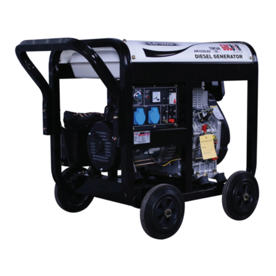
Page 4: Overall View Of The Generator
Overall view of the generator... -
Page 5: Chapter 1 Technical Specifications And Data
CHAPTER 1.TECHNICAL SPECIFICATIONS AND DATA 1-1Technical specifications and data MODEL GJD7000H GJD7000H-3 GJD7000S GJD7000S-3 GJD8000H GJD8000H-3 FREQUENCY 230/400 230/400 230/400 VOLTAGE MAXIMUM POWER POWER AMPERE PHASE VOLTAGE REGULATION POWER FACTOR 192FAE 188FAE 188FAE 188FAE 188FAE 192FAE ENGINE MODEL 88X75 88X75... -
Page 6: Chapter 2 Operating The Diesel Generator
CHAPTER 2 OPERATING THE DIESEL GENERATOR 2-1 General main points of safety during operation of the generator set. In order to operate the generator set safely,please follow all the instructions provided in this manual carefully. Doing so otherwise may lead to accidents and or equipment damage.... - Page 7 Fig.2-1 2-1.5 Other safety points Before operating this generator,all operators should have a good knowledge of how to break the circuit if any accidents occur.Also,all operators should be familiar with all the swRches and functions of the generator before using this machine.While operating the generator,wear safe shoes and suitable clothes during operation....
-
Page 8: Preparation Before Operation
Note:It is dangerous to overfill the fuel exhaust gas isabnormal,replace tank.Never exceed the red piston in the the air filter element.Never filter. start the diesel engine without the air filter. GJD7000S Type GJD7000H GJD7000S3 GJD7000H3 GJD8000S GJD10000S GJD16000S GJD8000H GJD8000S3 GJD10000S3... - Page 9 2-2.2 Filling engine oil Pouring inlet of lubricating oil Put the generator set at level state,Fill the lubri- cating oil to it till the inlet.At the same time.C- heck the oil level with dipstick.It is neecessary only toinsert the dipstick lightly.Caution:don’t ratate the dipstick....
- Page 10 2-2.3 Check the air filter (1)Loosen the butterfly nut,take the cover (Note:Only certain welder generator sets ofthe air filter off and take the air filter ele- have an electricfan incorporated on them.) ment out. Before starting the generator,make sure the Butterfly air switch is in the“off”position.Starting the generator with the switch in the“on”...
-
Page 11: Checking The Operation Of The Diesel Engine
2-4 Starting the generator set 2-2.5 The fuel and oil in a new engine is drained before sold.Before you start the 2-4.1 Manual starting. engine,please fill the fuel tank and engine Start the engine in accordance with procedures oil first.Then.check to see if there are air below:... - Page 12 2-4.2 Electric starting The procedures for preparing to start eh engine are the same as the manual starting engine. 1.Insert key into ignition and put it in the“off ”position. 2.Put the speed handle in the “Run”position. 3.TuITI the start switch clockwi~to the ‘‘START”position;to set the silent type,first turn it clockwise to the “RUN”(ON)position for 1-2 seconds.The electromagnetic iron will be triggered,now turn it clockwise to the“START”position....
-
Page 13: Procedures For Starting The Generator Set
2-5 Procedures for starting the generator set This procedure applies to the GJD series recoil starting style models .... -
Page 15: Proper Oper~Ion Of The Generator Set
2-6 Proper operation of the generator set 2-6.1 Operating the diesel engine 2-6.2 Checks during engine operation 1.Pre-heat the diesel engine for 3 min- 1. Check to see if there are abnormal noises. utes under no load conditions. 2. Check to see if the performance is 2.First check the height of the lubricat- good or bad.... - Page 16 2. Observe the pointerofthe voltmeter,it shouldpointto 230V/400V±5%(50Hz).(For 60Hz set,itwill be 240V±5%).Meanwhile putthe switchinthe GEN(genemtor)position. The AC voltage from the socket of the power supply canbe output. 3. When connecting devices to the generator,make sure to connect these devices in order. Connect the large loads onto the generator first.If everything is functional,...
-
Page 17: Stopping The Generator
2-8 Stopping the generator 1.Take the electrical load off the generator. 2.Putthe speedhandle inthe‘‘RUN”position and let the engine run for 3 minutes after unloading.Do not stop the diesel engine immediately let it warm down.Stopping the diesel engine suddenly may raise the temperature of the engine abnormally and lock the nozzle and damage the diesel engine.... -
Page 18: Chapter 3 Maintenance
CHAPTER 3 MAINTENANCE 3-1 Maintenance schedules Kepping your generator well maintained will prolong the life of your generator.Everything needs to be checked including the diesel engine,welder,generator,control cabinet,and frame.For overhauling procedures,please refer to the instruction manual of the relative subassembly.If you need these manuals,plsaes call our company and we will send you one. Before starting the maintenance,make sure the diesel engine is off.... - Page 19 3-1.1 Changing the engine oil(every l00 hours) 3-1.3 Fuel filter maintenance Take the oil cover out.Remove the oil drain 1. The fuel filter should be cleaned often to plug when the diesel engine is still hot.Be keep the engine running at maximum pe- careful of hot oil and hot engine as you may rformance....
-
Page 20: Storing For Long Periods Of Time
3-2 Storing for long periods of time If your generator needs to be stored for long periods of time,the following preparations should be made. 1. Start the diesel engine for 3 minutes then stop it. 2. When the engine is still hot,change the engine oil with new engine oil of the proper grade.... -
Page 21: Chapter 4 Troubleshooting
CHAPTER 4 TROUBLE SHOOTING 4-1 Troubleshooting procedures Causes of malfunction Remedy Not enough fuel Add enough fuel The switch of fuel is not at “OPEN”position Turn the switch of fuel to“OPEN” position High-pressure pump and nozzle do not inject fuel or the injected amount is less Disassemble the nozzle and adjust it at test table Speed control lever is not at “RUN”position Tum speed control lever to“RUN”... -
Page 22: Chapter 5 Part Listings
Chapter 5 Part Listings Open Frame Series unit... - Page 23 NO. Part Number Part Description KDF2500-07000 Cushion 2500 KDF6700-07000 Cushion 4000 KDF6700-04100 Bracket 6700 KDF7500-04100 Bracket 7500 KDF8500-04100 Bracket 8500 KD170F.178F.186 Air-cooled Diesel Engine FA.188FA.192F 4 KD186F-12000 Starting Motor KD170F-08200 2500 Muffler (Open Frame Type) KD178F-08200 4000 Muffler (Open Frame Type) KD186F-08200 6700,7500 Muffler (Open Frame Type) KD192F-08200...
- Page 24 KDF6700-3-02003A Three -phase AVR 6700,7500,8500 220/380 KDF6700-3-02003B Three -phase AVR 6700,7500,8500 127/220 KDF6700-3-02201 Stator 6700 3-Phase 220/380 KDF7500-3-02201 Stator 7500 3-Phase 220/380 KDF8500-3-02201 Stator 8500 3-Phase 220/380 KDF6700-3-02202 Stator 6700 3-Phase 127/220 KDF7500-3-02202 Stator 7500 3-Phase 127/220 KDF8500-3-02202 Stator 8500 3-Phase 127/220 KDF2500-08000 Battery Assembly 2500,4000 KDF6700-08000...
- Page 25 41 KDF6700-05002 Fuel Filler Pipe 42 GB/T6170-2000 Nut M6 43 KDF6700-05300 Fuel Tank Switch Assembly 44 GB/T3452.1-1992 O-Ring 45 GB/T819.2-2000 Screw 46 KDF6700-05003 Seal Plate 47 KDF6700-05004 Seal Washer 48 KD168F-01007 Seal Washe r 49 KDF6700-05400 Element Assembly 50 KDF6700-05500 Fuel Tank Weldment Assembly 51 KDF6700-05600 Oil Mark Assembly...
- Page 26 65 GB/T5787-1986 Bolt KDF2500-02002 Alternator Rare Cover 2500 KDF6700-02002 Alternator Rare Cover 4000,6700,7500,8500 67 GB/T5787-1986 Bolt M6X12 68 D104 Carbon Brush 69 GB/T5789-1986 Screw M5X 12 70 140616 Gratz Rectifier 71 SN001 Generator Serial Number KDF2500-02003 2500 AVR Open Frame, Single Phase KDF6700-02003 4000,6700,7500,8500 AVR,Open Frame, Single Phase KDF2500-02004...
- Page 27 KDF6700-3-03003B Instrument Panel 6700T,Electric Starter 220/380,E-Starter KDF6700-3-03004B Instrument Panel 6700T,Electric Starter 127/220,E-Starter KDF7500-3-03003B Instrument Panel 7500T,Electric Starter 220/380,E-Starter KDF7500-3-03004B Instrument Panel 7500T,Electric Starter 127/220,E-Starter KDF8500-3-03003B Instrument Pane 8500T,Electric Starter 220/380,E-Starter KDF8500-3-03004B Instrument Panel 8500T,Electric Starter 127/220,E-Starter 104 JK 425 Starting key KDF2500-03003A Instrument Panel 2500 Recoil Starter KDF2500-03003B...
- Page 28 Low-noise units Series Part Number Part Description Air Cooled Diesel Engine KD186FA 188FA 192F GB/T97.1-2000 Gasket 6 KDF6700-01001 Front Air Guide Plate 6700. 7500 KDF8500-01001 Front Air Guide Plate 85000 GB/T5783-2000 Bolt M8x16 GB/T93-1987 Elastic Washer 8 GB/T97.1-2000 Flat Gasket 8 GB/T5783-2000 Bolt M8x16 KDF6700-01002...
- Page 29 Part Number Part Description KDF6700-05100 Door Lock Assembly GB/T5783-2000 Bolt.M620 GB/T93-1987 Elastic Washer 6 10 GB/T96.2-2002 Big Gasket 6 11 KDF6700-05200 Casing Weldment 12 KDF6700-01001 Rear Plate Weldment 13 GB/T5783-2000 Bolt.M616 14 GB/T93-1987 Elastic Washer 6 15 GB/T96.2-2002 Big Gasket 6 16 KDF6700-05002 Damping Cushion of the Fuel Tank 17 KDF6700-05003...
- Page 30 Part Number Part Description KDF6700-06100 Right Side Plate Weldment GB/T5783-2000 Bolt.M6x16 KDF6700-06001 Air Cleaner Cover Plate Part Number Part Description KDF6700-04100 Radiating Plate GB/T5783-2000 Bolt.M6x16 GB/T93-1987 Elastic Washer 6 GB/T96-1985 Big Gasket 6 KDF6700-04200 Left Side Plate Weldment...
- Page 31 Part Number Part Description KDF6700Q-02000 6700 Alternator Assembly,Single Phase KDF7500Q-02000 7500 Alternator Assembly,Single Phase KDF8500Q-02000 8500 Alternator Assembly,Single Phase KDF6700Q-3-02001 6700 Alternator Assembly,Three Phase 380T KDF7500Q-3-02001 7500 Alternator Assembly,Three Phase 380T KDF8500Q-3-02001 8500 Alternator Assembly,Three Phase 380T KDF6700Q-3-02002 6700 Alternator Assembly,Three Phase 220T KDF7500Q-3-02002 7500 Alternator Assembly,Three Phase 220T KDF8500Q-3-02002...
- Page 32 Part Number Part Description GB/62-1988 Nut M6 KDF6700-08002 Pressure Plate of Batteryer 6 KDF6700-08001 Fasten rod of Battery KDF6700-08004 Base Plate of Battery GB/T5783-2000 Bolt M6x20 KDF6700-03001 Support Plate of Battery KDF6700-03200 Chassis Weldment KDF6700-03002 Tailstock Air Hole of Motor GB/T93-1987 Elastic Washer 5 10 GB/T5783-2000...
- Page 33 Part Number Part Description KDF6700-07000 Fuel Tank KDF6700-07200 Fuel Tank Cover KDF6700-07001 Filter Screen of Filling KDF6700-07100 Fuel Tank Weldment KDF6700-07300 Oil Indicator GB/T818-2000 Screw.M5x12 GB/T93-1987 Elastic Washer 5 GB/T97.1-2000 Flat Gasket 5 KDF6700-07002 Sheath 10 KDF6700-07003 Damping Sheath 11 GB/T5783-2000 Bolt.M6x30 12 GB/T97.1-2000 Flat Gasket 6...
- Page 34 KD186F-02015 Exhaust Pipe Washer6700、7500 KD192F-02015 Exhaust Pipe Washer8500 GB/T97.1-2000 Flat Gasket 8 GB/T93-1987 Elastic Washer8 GB/T6170-2000 Nut M8 KDF6700-08100 Exhaust Pipe Unit6700、7500 KDF8500-08100 Exhaust Pipe Unit8500 KDF6700-08200 Silent GeneratorMuffler Assembly 11 KDF6700-08300 GB/T5783-2000 Bolt.M8x16 GB/T5783-2000 Bolt.M8x30 KDF6700-08001 Outlet Tube of Tail Air Particle 13 Clip Clip I 12 KDF6700-08400...
- Page 35 Part Number Part Description GB/T818-2000 Screw M6x12 CP001 Digital Control Panel GB/T819.1-2000 Screw M4x12 SW01000 Boat shaped Switch ACV02001 AC Voltmeter DCS03001 DC Socket GB/T818-2000 Screw M4x30 GB/T6177.1-2000 Nut.M6 PL01 PVC Label 10 GB/T818-2000 Screw.M4x10 11 KDF6700-09001 Control Panel 12 GB/T5783-2000 Bolt M4x20 13 SW01001 Breaker...
Need help?
Do you have a question about the GJD7000H and is the answer not in the manual?
Questions and answers