Table of Contents
Advertisement
Quick Links
IFM500(영문) 1904.2.3 9:48 PM 페이지1
001 pdf-in
Head Office/Factory
687-5, Sangoan-ri, Hongcheon-eub, Hongcheon-gun,
Gangwon-do, Korea (zip.250-804)
Tel : +82-33-434-9041 Fax : +82-33-434-9043
Seoul Office/R&D
3F, Kwangsung Venture Plaza, 445, Daehung-dong, Mapo-gu,
Seoul, Korea, 121-080, Republic of korea
Tel : +82-2-714-2962 Fax : +82-2-714-2963
Customer Service Dept.
Tel : +82-2-714-2962 Fax : +82-2-714-2963
Advertisement
Table of Contents

Related Manuals for Bionics IFM-500


Summary of Contents for Bionics IFM-500
- Page 1 IFM500(영문) 1904.2.3 9:48 PM 페이지1 001 pdf-in Head Office/Factory 687-5, Sangoan-ri, Hongcheon-eub, Hongcheon-gun, Gangwon-do, Korea (zip.250-804) Tel : +82-33-434-9041 Fax : +82-33-434-9043 Seoul Office/R&D 3F, Kwangsung Venture Plaza, 445, Daehung-dong, Mapo-gu, Seoul, Korea, 121-080, Republic of korea Tel : +82-2-714-2962 Fax : +82-2-714-2963 Customer Service Dept.
- Page 2 IFM500(영문) 1904.2.3 9:48 PM 페이지2 001 pdf-in Operation Manual IFM-500 FETAL MONITOR Ver 1.4...
- Page 3 IFM500(영문) 1904.2.3 9:48 PM 페이지3 001 pdf-in...
-
Page 4: Table Of Contents
IFM500(영문) 1904.2.3 9:48 PM 페이지4 001 pdf-in able of Contents 1. INTRODUCTION 2. SAFETY PRECAUTIONS 2.1 Proper Environment for the use of IFM-500 2.2 Electrical Safety precaution 2.3 Maintenance and protection 2.4 Fuse Replacement 3. SPECIFICATIONS 3.1 Standard Specification 4. PRODUCT DESCRIPTION 4.1 Composition of IFM-500... - Page 5 IFM500(영문) 1904.2.3 9:48 PM 페이지5 001 pdf-in...
- Page 6 Preface Notes To Users ■ Thank you for purchasing the IFM-500 Fetal Monitor. To ensure safe operation and long term performance stability, it is essential that you fully understand the functions, operating and maintenance instructions by reading this manual before operating equipment.
- Page 7 IFM500(영문) 1904.2.3 9:48 PM 페이지2 001 pdf-in FETAL MONITOR Safety Symbols ■ The International Electrotechnical Commission (IEC) has established a set of symbols for medical electronic equipment which classify a connection or warn of any potential hazards. The classifications and symbols are shown below. Save these instructions.
-
Page 8: Introduction
001 pdf-in IFM-500 CHAPTER 1 INTRODUCTION Thank you for your purchase of BIONICS FETAL MONITOR (IFM-500). IFM-500 has been designed for the users’ best convenience. Exact and stable FHR(Fetal HeartRate), UC(Uterine Contraction) and FM(Fetal movement) extracted automatically by using Doppler Shift Frequency are displayed and recorded for monitoring up to fetal status. -
Page 9: Safety Precautions
: ① The equipment must be operated only by, or under supervision of, aqualified person. ② The IFM-500 is specified as Class I type BF equipment under the standard of IEC 60601-1 (Safety of Medical Equipment). - Page 10 IFM500(영문) 1904.2.3 9:48 PM 페이지5 001 pdf-in IFM-500 where the equipment is exposed to dust. ● where the equipment is exposed to high density oil vapor. ● where the equipment is exposed to salty atmosphere. ● where the equipment is exposed to explosive gas or dust.
-
Page 11: Electrical Safety Precaution
IFM500(영문) 1904.2.3 9:48 PM 페이지6 001 pdf-in FETAL MONITOR 2.2. Electrical Safety Precaution EQUIPOTENTIAL BONDING ; In hospital, doctors and patients are subjected to dangerous, uncontrollable compensating currents. These currents are due to the potential differences between connected equipment and touchable conducting parts as found in medical rooms. - Page 12 - Equipment not suitable for use in presence of a flammable anesthetic mixture - Continuous operation by standard of IEC 60601-1 (Safety of Electric Medical Equipment). Moreover, IFM-500 is complied with Class A for Noise-Emission, Level B for Noise- immunity, by standard of IEC 60601-1-2 (Electromagnetic Compatibility Requirements).
-
Page 13: Maintenance And Protection
IFM500(영문) 1904.2.3 9:48 PM 페이지8 001 pdf-in FETAL MONITOR 2.3. Maintenance and Protection ■ ■ Cleaning To keep the system and probe clean, rub them smoothly with a soft cloth soaked it in the warm ● water or dampened with alcohol at least once a month. Do not use lacquer thinner ethylene oxide or any other organic solutions, as this can destroy the membrane of the probe. -
Page 14: Fuse Replacement
IFM500(영문) 1904.2.3 9:48 PM 페이지9 001 pdf-in IFM-500 2.4. Maintenance and Protection 1. Open fuse drawer on the upper side of the appliance inlet, there will be the two small fuse holder. 2. Push the fuse holder toward the arrow direction, and pull the fuse holder toward the upper side of the appliance inlet. -
Page 15: Specifications
IFM500(영문) 1904.2.3 9:48 PM 페이지10 001 pdf-in FETAL MONITOR CHAPTER 3 SAFETY PRECAUTIONS 3.1. Standard Specification 1) Operating Frequancy : 2 MHz 2) Intenity : 10rm mW/cm or less 3) FHR Measurement - Dual FHR display and recording - Measurement range : 50 ∼ 240 bmp(beat per minute) - Fetal heart beat sound - Fetal heart beat rhythm lamp - Signal quality indication (Green: good, Red: noise present) - Page 16 IFM500(영문) 1904.2.3 9:48 PM 페이지11 001 pdf-in IFM-500 7) Set-up Function - Date and time - Record speed - Record contrast - Auto-record period - Upper and lower value for alarming 8) Power required - Input : 100 - 240V ~, 50/60 Hz - Power consumption : Abt.
-
Page 17: Product Description
FETAL MONITOR CHAPTER 4 PRODUCT DESCRIPTION 4.1. Composition of IFM-500 Open the packing box and check if main unit and all related accessories are staying in.Also check the breakage and damages which can be happen during transportation.If any related accessories are missing, please inquire the situation to seller. -
Page 18: Name Of Each Part
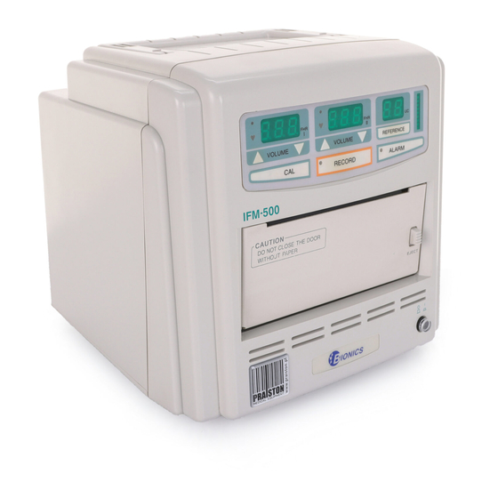
IFM500(영문) 1904.2.3 9:48 PM 페이지13 001 pdf-in IFM-500 4.2. Name of Each part ■ ■ Front panel Function (1) Front cover (2) Operating panel (3) Open knob (4) Power switch (5) Logo label (6) Door panel Product Description 13... - Page 19 IFM500(영문) 1904.2.3 9:48 PM 페이지14 001 pdf-in FETAL MONITOR Rear panel ■ ■ Mark RS-232C (7) Rear cover (8) Lift handle (9) Event marker socket : Connect Event Marker to this connector. (10) Serial port : Connect PC to this connector using by supplied cable. (option) (11) DOP I transducer port : Connect DOP probe to this connector.
- Page 20 IFM500(영문) 1904.2.3 9:48 PM 페이지15 001 pdf-in IFM-500 (13) Power inlet (14) Protect ground (15) Tocotransducer port : Connect UC probe to this connector. (16) Main label (17) Speaker Auxiliary equipment connected to the system interface must be certified according to the respective IEC standard (e.q.
- Page 21 IFM500(영문) 1904.2.3 9:48 PM 페이지16 001 pdf-in FETAL MONITOR ■ ■ Control panel Function (18) DOP I Select lamp (19) DOP I rhythm lamp (20) FHR I display (21) DOP I volume up button (22) DOP I volume down button (23) DOP Ⅱ...
-
Page 22: Installation
Please be sure following precautions for installing and use. - Use and keep IFM-500 at temperature and humidity 10 ~ 40。 C and 30 ~ 85 % respectively. - Check the connecting status of power cord and transducer cable for smooth using. -
Page 23: Recordfing Paper Installation
- Make the end of paper and end of door parallel. - Thermal printer head can be damaged if door cover are closed without paper. 5.3. Power Connection - Connect IFM-500 to AC power inlet(13) by using power cable. 18 Installation... -
Page 24: Set-Up Mode
IFM500(영문) 1904.2.3 9:48 PM 페이지19 001 pdf-in IFM-500 CHAPTER 6 SET-UP MODE 6.1. Initial Set-Up Time, date, Printer record speed, Record contrast, Auto-record period, FHR alarm limits,etc. are pre-setted as belows. And you can change the value as you like. -
Page 25: Set-Up Function
IFM500(영문) 1904.2.3 9:48 PM 페이지20 001 pdf-in FETAL MONITOR 6.2. Set-Up Function 6.2.1. Time & Date set-up function - Push “CAL” button for over 2 seconds, then you can hear “Beep” sound saying ready for setting-up. - Adjust year, month, date, hour, minute and seconds with FHR I volume buttons - Adjust numeric values with Function button. - Page 26 IFM500(영문) 1904.2.3 9:48 PM 페이지21 001 pdf-in IFM-500 6.2.2. FHR Alarm set-up function - Push “ ALARM” button for over 2 seconds, and FHR alarm set-up function starts with “Bee” sound. - Set upper and lower limit by using FHR I volume up and down button.
- Page 27 IFM500(영문) 1904.2.3 9:48 PM 페이지22 001 pdf-in FETAL MONITOR 6.2.3. Record speed set-up function - Push “ R E F” button for over 2 seconds, and record speed set-up function starts with “Bee” sound. - Then, “REC” on FHR I display and “ SPd” on Function display are displayed respectively. - UC display can be displayed like “...
- Page 28 IFM500(영문) 1904.2.3 9:48 PM 페이지23 001 pdf-in IFM-500 6.2.4. Record contrast set-up function - Push “ R E F” button for over 2 seconds, and record period set-up function starts with “Bee” sound. - Then, “R E C” on FHR I display and “ C o n” on Function display are displayed respectively.
- Page 29 IFM500(영문) 1904.2.3 9:48 PM 페이지24 001 pdf-in FETAL MONITOR 6.2.5. Auto-record period set-up function - Push “ REF”button for over 2 seconds, and auto-record period set-up function starts with “Bee” sound. - Then, “REC” on Function display and “ Prd” on Function display are displayed respectively. - UC display can be displayed like “...
- Page 30 IFM500(영문) 1904.2.3 9:48 PM 페이지25 001 pdf-in IFM-500 FHR Ⅰ Function ▲ ▼ Function up / down button Set-up Mode 25...
-
Page 31: Operation
IFM500(영문) 1904.2.3 9:48 PM 페이지26 001 pdf-in FETAL MONITOR CHAPTER 7 OPERATION ■ Initial status (Power on) When you turn on the unit, it will be seen like belows on displays which are blinking for 3 times while hearing “ Beep” sound. After this, unit are going into stand-by status for operation. Function FHR Ⅰ... - Page 32 IFM500(영문) 1904.2.3 9:48 PM 페이지27 001 pdf-in IFM-500 ■Buttons DOP I volume up / down : Fetal heart beat sound of DOP I is going up/down. In set-up mode, values are going up/down. Function up / down : In set-up mode, values are going up/down.
-
Page 33: Fhr(Fetal Heart Rate)
IFM500(영문) 1904.2.3 9:48 PM 페이지28 001 pdf-in FETAL MONITOR 7.2. FHR (Fetal Heart Rate) ■ ■ In case of transducer disconnection FHR I display LED is in off status. ■ ■ In case of DOP transducer connection 1) Selection indicator lamp turned on is indicating related Dop transducer is connected. 2) If there is no signal inputed to the transducer connected, “0”... -
Page 34: Uc(Uterine Contraction)
IFM500(영문) 1904.2.3 9:48 PM 페이지29 001 pdf-in IFM-500 7.3. UC (Uterine Contraction) ■ ■ In case of transducer disconnection UC value display and LED bar are turn off. ■ ■ In case of tocotrnasducer connection 1) UC display and LED bar is displaying current value respectively. -
Page 35: Evevnt Marking
- Push power switch(14) so that you will see green light on front face of power switch. - After turned on IFM-500, it will start operation with the “ Beep” sound. - Self-test operation will be started if calibration button on front panel are pushed. -
Page 36: How To Use Transducers
HOW TO USE TRANSDUCERS 8.1. Doppler measurement method IFM-500 is designed to measure FHR by using ultrasound which is high frequency waves above the range of audible to the human ears. Ultrasound is transmitted to fetal heart wall through abdominal of pregnant woman and ultrasound frequancy reflected by moving heart wall is changed by movement of fetal heart wall. - Page 37 IFM500(영문) 1904.2.3 9:48 PM 페이지32 001 pdf-in FETAL MONITOR When fetus is heading down-ward or up-ward, you have to pay attention on placing the transducer. Please put the transducer around the navel of patient. ② Moving the transducer slowly, search for the position where you can hear heart-beating more clearly.
-
Page 38: Uc Measurement Method
IFM500(영문) 1904.2.3 9:48 PM 페이지33 001 pdf-in IFM-500 8.2. UC measurement method Tocotransducer is used in measuring external uterine contraction with the help of belt. Tocotransducer affixed on maternal abdominal wall is measuring UC by the pressure made by uterine contraction. -
Page 39: Error Message And Countermesure
IFM500(영문) 1904.2.3 9:48 PM 페이지34 001 pdf-in FETAL MONITOR CHAPTER 9 ERROR MESSAGE AND COUNTERMEASURE Error message will be displayed on FHR I, II display LED. When error messages are occurs, please refer to following chart for error message signal and countmeasure. Factors causing Alarming Countermeasure... -
Page 40: Recording Paper
IFM500(영문) 1904.2.3 9:48 PM 페이지35 001 pdf-in IFM-500 CHAPTER 10 RECORDING PAPER IFM-500 will start recording with one pushing of “REC” button and output from of recording is as below. ① ③ ④ ⑥ ⑦ ① Use and non-use indication of DOP I transducer.(OFF→not using, ON→ using) ②... - Page 41 IFM500(영문) 1904.2.3 9:48 PM 페이지36 001 pdf-in FETAL MONITOR ⑩ Recording range of uterine contraction. ⑪ Arrow marked by event marker. ⑫ Time is recorded every five minutes. If any data recorded on printer are changed, new data will appar on top of recording paper. (Ex: DOP I transducer : on - off and off - on, Tocotransducer : on - off and off - on, Change of upper and lower limit value of alarm function,...
-
Page 42: Afterservice
If there are any problems with the equipment, please follow the steps below : Contact the BIONICS Oversea Service Department immediately. After gathering the model name, Serial Number, date of purchase, and description of the problem contact BIONICS with the information shown below. -
Page 43: Warranty
■ Cosmetic defects or deterioration will not be refinished or replaced. The costs of training materials, or supplies are not covered. ■ BIONICS Corp. will not be responsible for any loss, dame, or injury resulting from delay in rendering service under this warranty. - Page 44 Fast Transients/Bursts : IEC 801-5 : d1993 [DM=1kV: CM=2kV] Surges : Supplementary Information The devices are Class IIb. The devices were tested in a typical configuration of a BIONICS IFM-500 Fetal monitor. (Quality Control Team Manager - Kwak Dong Hun)
Need help?
Do you have a question about the IFM-500 and is the answer not in the manual?
Questions and answers