Advertisement
Quick Links
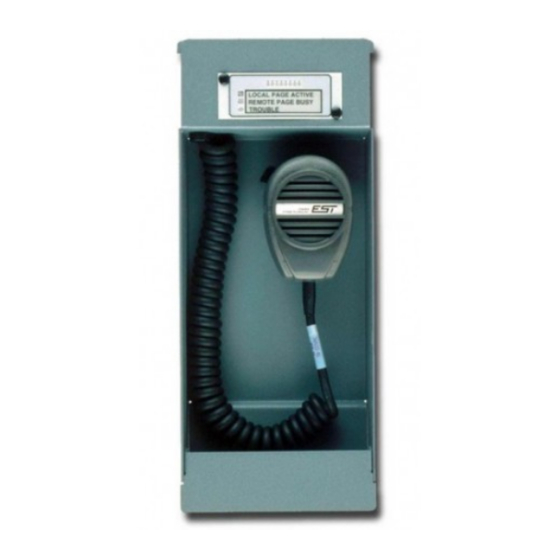
3-REMICA Remote Paging
Microphone Installation Sheet
Description
The 3-REMICA provides remote paging capability throughout a
building or campus. Each 3-REMICA has two inputs for connecting
other remote microphone units. Cascading remote microphones in this
manner provides up to 63 stations on the paging circuit.
Note:
Remote microphone units may not be cascaded more than six
deep (more than six units in a single circuit path).
The 3-REMICA occupies two slot positions in a remote annunciator
cabinet. When installed in a cabinet with an annunciator controller, the
3-REMICA must occupy the slot positions next to the controller.
The 3-REMICA housing assembly provides standoffs for mounting a
Signature single input module when the system application requires
electrical supervision. The 3-REMICA trouble relay contacts change
state when an electrical short or open is detected on either the
microphone audio or key inputs, or when power to the unit is
interrupted.
Configuration
Set the jumpers as shown in the table below. Refer to Figure 1.
When AUDIO_OUT is connected to a:
3-ASU Rev 11 or earlier [1]
3-ASU Rev 12 or later [1]
3-REMIC series remote paging microphone
[1] The revision number is stamped on the front of the ASU board,
bottom right corner.
© 2018 United Technologies Corporation
Installation
Install and wire this module in accordance with applicable national and
local codes, ordinances, and regulations. Refer to Figure 1.
Caution:
connections.
Note:
shipped with 1.8 kΩ terminating resistors installed in the remote
microphone key inputs. Remove these resistors when connecting
upstream 3-REMIC series remote paging microphones.
To install the 3-REMICA:
1. Remove the top module retainer bracket on the inner door of the
remote annunciator.
2. Loosen the bottom module retainer bracket.
3. Insert the 3-REMICA into the bottom module retainer bracket next
to the annunciator panel controller.
4. Tilt the 3-REMICA forward until the top touches the inner door.
5. Tighten the bottom module retainer bracket.
6. Secure the top module retainer bracket to the inner door.
7. If installed next to an annunciator panel controller, connect the
cable assembly from P3 on the annunciator panel controller to P4
on the 3-REMICA.
8. Attach the rubber stoppers provided, to the backbox studs located
directly behind the 3-REMICA assembly, to avoid shorting
components on the electronics board.
Figure 1: Card layout
Wiring
JP1
JP2
A
A
Wire the 3-REMICA as shown in Figure 2.
A
Remove
Notes
B
B
•
All wiring is supervised and power-limited.
•
Remove the 1.8 kΩ terminating resistors across terminals TB1-12
and TB1-13, and TB1-16 and TB1-17 if connected to an upstream
3-REMIC series remote paging microphone.
•
AUDIO_OUT and KEY_OUT wires must be enclosed in conduit.
1 / 2
Ensure the 24 VDC riser is deenergized before making cable
To prevent trouble events during installation, the 3-REMICA is
TB1
JP2
B
A
P3
P/N 387466-EN • REV 005 • ISS 15JUN18
JP1
B
A
GAIN
ADJUST
P4
Advertisement

Subscribe to Our Youtube Channel
Related Manuals for Edwards 3-REMICA


Summary of Contents for Edwards 3-REMICA
- Page 1 3. Insert the 3-REMICA into the bottom module retainer bracket next to the annunciator panel controller. 4. Tilt the 3-REMICA forward until the top touches the inner door. 5. Tighten the bottom module retainer bracket. 6. Secure the top module retainer bracket to the inner door.
- Page 2 21 to 27 VDC talk switch on the microphone. If you get feedback through the system Current 52 mA speakers, adjust the gain on the 3-REMICA until the feedback is eliminated. See Figure 1 for the location of the gain adjustment. Wiring Size 14 AWG (1.5 mm²) max.
Need help?
Do you have a question about the 3-REMICA and is the answer not in the manual?
Questions and answers