
Related Manuals for PLASTOMATIC CAFE

Summary of Contents for PLASTOMATIC CAFE
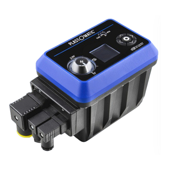
- Page 1 SERIES CAFÉ MULTI-VOLTAGE ELECTRIC ACTUATORS Installation, operation, & maintenance instructions...
-
Page 2: Table Of Contents
CONTENTS SAFETY INSTRUCTIONS SPECIFICATIONS DIMENSIONS INSTALLATION WIRING ON/OFF MODULATION INPUT/OUTPUT OPERATION ON/OFF MODULATION INPUT/OUTPUT... - Page 3 CAFE PARTS LIST Small DIN Connector Small DIN Cap x1 CAFE Actuator x1 Large DIN Connector x1 (10 o’clock Ground) x1 For Shipping Purposes Only For Shipping Purposes Only Plastic Plastic Gland Rubber Gland Small DIN Large DIN Cap Large DIN Cap...
- Page 4 ON/OFF CAFE NITRO PARTS LIST Small DIN Connector Small DIN Cap x1 CAFE NITRO Actuator x1 Large DIN Connector x1 (10 o’clock Ground) x1 For Shipping Purposes Only For Shipping Purposes Only Plastic Plastic Gland Rubber Gland Small DIN Large DIN Cap...
- Page 5 CAFE NITRO W/ CONTROL PARTS LIST Small DIN Connector Small DIN Connector CAFE NITRO Actuator x1 Large DIN Connector x1 (10 o’clock Ground) x1 (6 o’clock Ground) x1 For Shipping Purposes Only For Shipping Purposes Only Plastic Plastic Gland Rubber Gland...
-
Page 6: Safety Instructions
SAFETY INSTRUCTIONS Damage caused by non-compliance to these instructions will not be covered by our warranty. Read these instructions BEFORE installing or connecting the actuator. Electric actuators operate with the use of live electricity. It is recommended that only qualified electricians or people instructed in accordance with electrical engineering, and familiar with local electrical, health and safety directives, be involved in the connection of these actuators. -
Page 7: Specifications
SPECIFICATIONS Sizes 3/8"-2" Ball Valves CAFE Actuator CAFE NITRO 24 Vdc, 24 Vac, 110-240 Vac Input Voltage (+1.1 V / -0.85 V 24 Vdc, 24 Vac, 110-240 Vac Frequency DC, 50Hz/60Hz DC, 50Hz/60Hz Working Time 0-90° No Load) ±10% 5 seconds preset... -
Page 8: Dimensions
DIMENSIONS 5.35 in 135.89 mm 7.40 in 187.85 mm 3.73 in 94.62 mm 4.51 in 114.49 mm 4.51 in 114.49 mm 3.73 in 94.62 mm... -
Page 9: Installation
INSTALLATION SIZE MODEL CAFE/CAFEN-037 3/8" 4.13 104.8 7.40 187.8 4.05 102.9 6.48 164.7 2.75 69.9 3.73 94.6 4.00 101.6 CAFE/CAFEN-050 1/2" 4.13 104.8 7.40 187.8 4.05 102.9 6.48 164.7 2.75 69.9 3.73 94.6 4.00 101.6 CAFE/CAFEN-075 3/4" 4.75 120.7 7.40 187.8 4.05 102.9 6.90 175.2 3.25 82.6... -
Page 10: Wiring
INSTALLATION MOUNTING TO PLAST-O-MATIC BALL VALVE MOUNTING PLATE DETAIL Valve Size... - Page 11 All pole disconnection is required. Use copper conductors only. BEFORE connecting, ensure the voltage to be CAFE actuators are multi-voltage capable with Water tightness: Ensure that all rubber gaskets are correctly installed when securing the Field applied is within the range shown on the ID label.
-
Page 12: Input/Output
ON/OFF WIRING (3 WIRES AC/DC) PINOUT INPUT POWER ANALOG IN/OUT DISCRETE OUTPUT (RELAYS) – (GND) – – – – COMMON – – (GND) – – – – COMMON – – (GND) – – – – COMMON **OFF – – (GND) –... - Page 13 (GND) – – – – COMMON **OFF – – DISCRETE OUTPUTS: Chart indicates settings from Factory. Configuration can be changed via User Interface *The corresponding Relay closes to indicate ON position **The corresponding relay closes to indicate OFF position plastomatic.com...
- Page 14 MODULATION WIRING (mA) OR (V) PINOUT INPUT POWER ANALOG IN/OUT DISCRETE OUTPUT (RELAYS) – (GND) COMMON – COMMON **OFF – – (GND) COMMON – COMMON **OFF – DISCRETE OUTPUTS: Chart indicates settings from Factory. Configuration can be changed via User Interface. *The corresponding Relay closes to indicate ON position **The corresponding relay closes to indicate OFF position...
- Page 15 – (GND) COMMON – A-D-D0 – COMMON **OFF – DISCRETE OUTPUTS: Chart indicates settngs from Factory. Configuration can be changed via User Interface. *The corresponding Relay closes to indicate ON position **The corresponding relay closes to indicate OFF position plastomatic.com...
- Page 16 INPUT/OUTPUT WIRING INTERNAL CONFIGURATIONS (ON/OFF) DISCRETE CONTROL (MODULATION) ANALOGUE INPUT POWER CONTROL IN/OUT (ALL MODELS) DISCRETE OUTPUTS (MODBUS) COMM. CONTROL RS 485 VOLTAGE FREE RELAYS...
-
Page 17: Operation
(ON/OFF) DISCRETE (ON/OFF) DISCRETE (MODULATION) ANALOGUE CONTROL INPUT – INPUT CONTROL INPUT – INPUT CONTROL IN/OUT POWER - 3 WIRES, AC/DC POWER - 2 WIRES, DC (MODBUS) COMM. (ALL MODELS) DISCRETE CONTROL - RS485 OUTPUTS – VOLTAGE FREE RELAYS plastomatic.com... - Page 18 INPUT/OUTPUTS MODBUS REGISTRY TABLE Value ModBus Register Description Name Min Value Max Value (Default/Prog) Hard Fault Over Temp Overload High Fault Code Power Loss 40000 Signal Loss Dual Signal Input Mode Modbus High Current Position Position 40001 High Set Point Setpoint 40002 High...
- Page 19 OPERATION FEATURES LED Ring Manual Indicator Display Drive Keypad Visual Indicator Discrete Output Discrete Control Input Voltage Free Relays Input Power Analog Control IN/OUT or Comm. Control – Modbus plastomatic.com...
- Page 20 OPERATION FEATURES Manual Override: Use a 4 mm hex wrench to drive the actuator manually. Rotating the manual drive counter clockwise will open the valve in a standard orientation. Rotating the manual drive clockwise will close a valve that is in the open position.
- Page 21 5. Closing 6. Torque limit engaged, moving from close to open 7. Torque limit engaged, moving from open to close 8. Actuator in MANUAL or KEYPAD mode 9. Actuation feedback complete 10. Signal loss 11. Over temperature 12. Overload plastomatic.com...
- Page 22 OPERATION LED RING INDICATOR RUNNING STATES LED RING INDICATOR RUNNING STATES MODBUS ACTUATOR ACTUATOR OPERATIONAL STATUS 1. No power detected 2. In position open 3. In position close 4. Opening 5. Closing 6. Torque limit engaged, moving from close to open 7.
- Page 23 Actuator in MANUAL or KEYPAD mode: LED ring indicator blinks yellow indicating, that the actuator is in manual mode. Actuator can be controlled via the keypad or 4mm Hex Wrench, depending on the setting. Only available on actuators with Display and keypad. plastomatic.com...
- Page 24 OPERATION INITIALIZATION DISPLAY WELCOME DISPLAY FIRMWARE & HARDWARE VERSION INFORMATION Indicates the type of Actuator: ON/OFF, Modulating, or Modbus STATUS DISPLAY Type of IN/OUT control signal Actual Position as a % of working angle Desire Position as a % of working angle Power Source, Main or Battery Last Triggered Alarm Short cut to Drive Control...
- Page 25 Actuators with Fail Safe will switch to Batt (Battery) at power loss. STATUS display will show the last triggered alarm during a failed operation. Triggered alarms during failed operation are: power loss, over torque, over temperature, signal loss, concurrent signal, and hardware failure. plastomatic.com...
- Page 26 OPERATION MAIN MENU MENU Display gives access to the root menu. The main menu is categorized as Alarms, Control, Language and Maintenance. Each category contains sub- menus that are specific to the type of actuator; ON/OFF, Modulating, Modbus. Alarms: Enter this sub-menu to reset any of the triggered alarms presented in the STATUS display.
- Page 27 > Language Maintenance Maintenance Maintenance ALARMS CONTROL LANGUAGE (Power Loss),(Signal > Operation English* Loss), (Overload), (Over Speed Espanol Temp), (Hard, Fault) Power Loss (Dual Signal) Comm Loss SAVE > Reset NEXT (OK) CONTROL Hard Monitor Anti condensation Password Scheduler plastomatic.com...
- Page 28 OPERATION (ON/OFF) MAIN MENU AND SUB-MENU MENU Alarms Record of the last three triggered alarms will Control be saved in display. Language Scheduler is only available in ON/ OFF > Maintenance actuators with Display, Keypad and RTC kit. Consult Factory. MAINTENANCE >...
- Page 29 Dead Band Dead Band NEXT NEXT NEXT OPERATION SPEED POWER LOSS Normal Closed* 100 % Open Normal Opened Increase Close* Decrease Hold > SAVE MENU Angle > SAVE MENU > SAVE MENU ANGLE 50 % Increase Decrease > SAVE MENU plastomatic.com...
- Page 30 OPERATION (ON/OFF) CONTROL AND SUB-MENU OPTIONS MENU Operation OPERATION Normal Closed operation is the Speed default. Actuator will close a valve when responding to an OFF signal or minimum > Power loss proportional control value. Actuator will open Dead Band a valve when responding to an ON signal or max.
- Page 31 Battery: 8.52 V Decrease New Password Run Time: 0 0 0 0 > MENU > SAVE MENU > SAVE MENU MENU LOGIN ON/OFF Dead Band Enter Password Hardware Monitor 0 0 0 0 Anticondensation Password >OK > LED >SAVE plastomatic.com...
- Page 32 OPERATION (ON/OFF) CONTROL AND SUB-MENU OPTIONS MENU Hardware Monitor SCHEDULER Selected models include an Event scheduler . Two events for valve OPEN/ Anticondensation CLOSE can be set up per day . This feature must be turned ON prior to being used. DATE & TIME must be updated for the internal clock to synchronize with the real time clock.
- Page 33 OPERATION (ON/OFF) MAINTENANCE AND SUB-MENU OPTIONS plastomatic.com...
- Page 34 OPERATION (ON/OFF) MAINTENANCE AND SUB-MENU OPTIONS CALIBRATION Use this display to set the closed and open position for the actuator. Select “Move” and then use < > to rotate counter clockwise or clockwise respectively. After the desired point is achieved select Set Closed or Set Opened.
- Page 35 > Relay Outputs Relay Outputs Third Angle > Third Angle Factory Setting Factory Setting RELAY ANGLE TA3 > Relay 1 Relay 2 Increase Decrease >SAVE MENU >SAVE MENU RELAY 1 > Status Open* Status Close Fault Force Close Force Open plastomatic.com...
- Page 36 OPERATION (ON/OFF) MAINTENANCE AND SUB-MENU OPTIONS MAINTENANCE Relay Outputs Third Angle > Factory Setting FACTORY SETTINGS > Keep Settings Factory Set. FACTORY SETTINGS Enter Password 0 0 0 0 >SAVE MENU...
- Page 37 Control Language Language > Language Maintenance Maintenance Maintenance ALARMS CONTROL LANGUAGE (Power Loss),(Signal > Operation English* Loss), (Overload), (Over Speed Espanol Temp), (Hardware) Power Loss Comm Loss SAVE > Reset (OK) NEXT CONTROL Dead Band Hard Monitor Anticondensation Password plastomatic.com...
- Page 38 OPERATION (MODULATION) MAIN MENU AND SUB-MENU MENU ondition Record of the last three triggered alarms will Alarms be saved in display. Overload, Over Temp, Control and Hard Fault are considered critical Language alarms and must be reset via this menu. User should clear the condition that Maintenance >...
- Page 39 > Power loss Comm Loss Comm Loss Comm Loss NEXT NEXT NEXT OPERATION SPEED POWER LOSS Normal Closed* 100 % Open Normal Opened Increase Close* Decrease Hold >SAVE MENU Angle >SAVE MENU >SAVE MENU ANGLE 50 % Increase Decrease >SAVE MENU plastomatic.com...
- Page 40 OPERATION (ON/OFF) CONTROL AND SUB-MENU OPTIONS MENU Operation Speed Power loss > Comm Loss NEXT COMM LOSS Open Close* Hold Angle >SAVE MENU ANGLE 50 % Increase Decrease >SAVE MENU...
- Page 41 Hardware Monitor > Hardware Monitor Hardware Monitor Anticondensation Anticondensation > Anticondensation Password Password Password DEAD BAND HARDWARE MONITOR ANTICONDENSATION Load: 0 mA 82°F Increase Int. Temp: 130°F Increase Decrease Battery: 8.52 V Decrease Run Time: >SAVE MENU >MENU >SAVE MENU plastomatic.com...
- Page 42 OPERATION (MODULATION) CONTROL AND SUB-MENU OPTIONS MENU MENU Dead Band Dead Band DEAD BAND Default setting is 0%. Move Hardware Monitor Hardware Monitor cursor to "increase" or "decrease" and then press to change % in relation to working Anticondensation Anticondensation angle up to 5%.
- Page 43 Compensation NEXT NEXT NEXT CALIBRATION ANALOG IN ANALOG OUT Move > 0-10 V* > 0-10 V* Position: 2-10 V 2-10 V Set Closed 0-20 mA 0-20 mA Set Opened 4-20 mA 4-20 mA >SAVE MENU >SAVE MENU >SAVE MENU plastomatic.com...
- Page 44 OPERATION (MODULATION) MAINTENANCE & SUB-MENU OPTIONS MAINTENANCE Calibration CALIBRATION Use this display to set the Analog In closed and open position for the actuator. Select “Move” and then use < > to rotate Analog Out counter-clockwise or clockwise respectively . >...
- Page 45 Factory Settings Factory Settings Factory Settings NEXT NEXT NEXT OVERLOAD HYSTERESIS DRIVE > 1 sec* Auto 2 sec Increase > Keypad 3 sec Decrease Manual Persist >SAVE MENU >SAVE MENU >SAVE MENU KEYPAD CONTROL Setpoint: > Increase Decrease MENU plastomatic.com...
- Page 46 OPERATION (MODULATION) MAINTENANCE & SUB-MENU OPTIONS MAINTENANCE MAINTENANCE Overload Overload OVERLOAD Use this display to set the time Hysteresis Hysteresis delay for overload detection. Default is 1 sec. Persist will keep trying the operation 5 Drive Drive consecutive times. Always SAVE the selection >...
- Page 47 Control Language Language > Language Maintenance Maintenance Maintenance ALARMS CONTROL LANGUAGE (Power Loss),(Signal > Operation English* Loss), (Overload), (Over Speed Espanol Temp), (Hardware) Power Loss Comm Loss SAVE > Reset (OK) NEXT CONTROL Dead Band Hard Monitor Anticondensation Password plastomatic.com...
- Page 48 OPERATION (MODBUS) MAIN MENU AND SUB-MENU MENU Alarms Control Language > Maintenance MAINTENANCE > Calibration Network Compensation Overload NEXT MAINTENANCE Hysteresis Drive Relay Outputs Factory Setting...
- Page 49 By default the settng is Hold. Only the selection. available for control signals 2-10V, 4-20 mA. > SAVE MENU SPEED 100% is the default . Move the cursor Always save the selection. to "increase" or "decrease" and then press to change %. plastomatic.com...
- Page 50 OPERATION (MODBUS) CONTROL AND SUB-MENU OPTIONS MENU Operation Speed Power loss > Comm Loss NEXT COMM LOSS Open Closed Hold* > Angle > SAVE MENU ANGLE 50 % > Increase Decrease > SAVE MENU...
- Page 51 Hardware Monitor Anticondensation Anticondensation > Anticondensation Password Password Password DEAD BAND HARDWARE MONITOR ANTICONDENSATION Load: 0 mA 0°F Increase Int. Temp: 153°F > Increase Decrease Battery: 8.47 V Decrease Run Time: OFF* > SAVE MENU > MENU > SAVE MENU plastomatic.com...
- Page 52 OPERATION (MODBUS) CONTROL AND SUB-MENU OPTIONS MENU MENU Dead Band Dead Band DEAD BAND Default setting is 0%. Move Hardware Monitor Hardware Monitor cursor to "increase" or "decrease" and then press to change % in relation to working Anticondensation Anticondensation angle up to 5%.
- Page 53 NEXT CALIBRATION NETWORK NETWORK Move > Node Node Position Baud Rate > Baud Rate Set Closed Set Opened > SAVE MENU > SAVE MENU > SAVE MENU NODE NETWORK 9600 Increase 19200* Decrease 57600 >SAVE MENU > SAVE MENU plastomatic.com...
- Page 54 OPERATION (MODBUS) MAINTENANCE & SUB-MENU OPTIONS MAINTENANCE MAINTENANCE Calibration Calibration CALIBRATION Use this display to set the Network Network closed and open position for the actuator. Select “Move” and then use < > to rotate > Compensation Compensation counter-clockwise or clockwise respectively. Overload >...
- Page 55 > Relay 1 Increase > Keypad Relay 2 Decrease Manual > SAVE MENU >SAVE MENU > SAVE MENU KEYPAD CONTROL RELAY 1 Setpoint: > Status Open > Increase Status Close Decrease Fault Force Close MENU Force Open > SAVE MENU plastomatic.com...
- Page 56 OPERATION (MODBUS) MAINTENANCE & SUB-MENU OPTIONS MAINTENANCE Hysteresis OVERLOAD Use this display to set the time Drive delay for overload detection. Default is 1 sec. Persist will keep trying the operation 5 Relay Output consecutive times. Always SAVE the selection >...
- Page 57 ENGINEERED & ASSEMBLED IN USA plastomatic.com...
- Page 58 Plast-O-Matic Valves, Inc. 1384 Pompton Avenue Cedar Grove, NJ 07009 USA (973) 256.3000 Fax (973) 256.4745 PRINTED IN USA...
Need help?
Do you have a question about the CAFE and is the answer not in the manual?
Questions and answers