
Related Manuals for R2Sonic 2026

Summary of Contents for R2Sonic 2026
- Page 1 SONIC 2026/2024/2022 BROADBAND MULTIBEAM ECHOSOUNDERS Operation Manual V6.3 Revision 012 (05NOV2022) Part No. 96000001...
- Page 2 Page 2 of 254 Version r012 Date 05-11-2022 Part No. 96000001...
- Page 3 Copyright license R2Sonic LLC is solely responsible for the content of this manual. Neither this manual nor any part of this manual may be copied, translated, distributed or modified in any manner without the express written approval of R2Sonic LLC.
- Page 4 Export Control Classification Number (ECCN) 6A991 and 6A001, a minor modification has been made in the range and frequencies available in the R2Sonic Multibeam Echosounder family only for those systems that are submerged to 100 metres depth or greater.
-
Page 5: Table Of Contents
Sonic 2026 System Specification ................... 25 Sonic 2024 System Specification ................... 25 Sonic 2022 System Specification ................... 26 Sonic 2026 Dimensions and Weights ..................26 Sonic 2024 Dimensions and Weights ..................26 Sonic 2022 Dimensions and Weights ..................27 Sonic 2026/2024/Sonic 2022 Electrical Interface ..............27 Sonic MBES Ping Rates (SV = 1500.00m/sec) ............... - Page 6 SONAR INTERFACE MODULE (SIM) INSTALLATION and INTERFACING ........49 Sonar Interface Module (SIM) ....................49 4.1.1 Physical installation ....................... 49 4.1.2 Electrical and Interfacing ....................50 4.1.3 Serial Communication ....................57 4.1.4 Time and PPS input ....................... 57 4.1.5 Motion Input ......................... 58 4.1.6 SVP input ........................
- Page 7 5.6.8 Mission Mode ....................... 77 5.6.9 Imagery ......................... 77 5.6.10 Roll Stabilize and Pitch Stabilize ................... 81 5.6.11 Dual Head Mode (Also see Appendix VII, Section 13.9) ..........82 5.6.12 TruePix™, Snippets, Water Column Enable and Intensity Enable ........ 84 5.6.13 Water Column Data Collection ..................
- Page 8 RangeTrac™ – Sonic Control automatically sets correct range ........108 5.16.3 Power: 191 – 221 dB ....................108 5.16.4 Pulse Width: 15µsec – 1115µsec (Sonic 2026 max is 2000µsec) ........ 108 5.16.5 Gain: 1 – 45 ......................... 109 5.16.6 Depth Gates: GateTrac™ ..................... 109 5.17...
- Page 9 I2NS DB9 Connections ....................127 Setup in Sonic Control ......................128 7.4.1 Network Setup ......................128 7.4.2 Applanix Group 119 specific to R2Sonic SIMINS ............129 7.4.3 Sensor Setup ....................... 130 7.4.4 INS Monitor (Alt+I) ..................... 130 Measuring IMU Offsets ...................... 132 7.5.1...
- Page 10 8.6.4 Distance ........................150 8.6.5 Deploying and recovering the Sound Velocity Probe ..........150 APPENDIX III: Multibeam Surveying .................. 153 Introduction ......................... 153 Survey Design ........................153 9.2.1 Line Spacing ......................... 153 9.2.2 Line Direction ......................153 9.2.3 Line Run-in ........................154 Record Keeping ........................
- Page 11 11.7.2 Feature chose for the test ..................169 11.7.3 Water depth ....................... 170 11.7.4 Use predefined survey lines ..................170 11.7.5 Speed.......................... 170 11.7.6 Vessel line up ......................170 11.7.7 Pole variability ......................170 11.8 Improving the Patch Test and Patch Test results .............. 171 11.8.1 Need to collect sufficient data ..................
- Page 12 GUI Commands, Binary Format ..................206 14.5.1 GUI Command Line Switches ..................207 14.6 Command Examples Sent to the Sonar Head and SIM ............208 15 APPENDIX IX: R2Sonic Uplink Data Formats ............... 211 15.1 Introduction ......................... 211 15.2 General Notes ........................211 15.3...
- Page 13 15.13 Device Status Format ......................230 15.14 Data Playback Using Bit-Twist .................... 231 15.14.1 Introduction ........................ 231 15.14.2 Capturing Data ......................231 15.14.3 Editing Data ........................ 232 15.14.4 Data Playback ......................233 16 APPENDIX X: Drawings ...................... 235 Page 13 of 254 Version r012 Date...
- Page 14 Page 14 of 254 Version r012 Date 05-11-2022 Part No. 96000001...
- Page 15 Figure 5: Sonic 2022 Acoustic Centre, as Mounted ................30 Figure 6: Sonic 2026 Acoustic Centre ....................31 Figure 7: Sonic 2026 Acoustic Centre, as mounted ................31 Figure 8: Sonic 2024 and Sonic 2022 on the mounting frame ............. 33 Figure 9: Topside of Receive Module ....................
- Page 16 Figure 56: Sonar Operation Settings window ..................69 Figure 57: Operating Frequency Selection ................... 70 Figure 58: 90 – 100 kHz Low frequency option for Sonic 2026 ............71 Figure 59: Ping Rate Limit ........................71 Figure 60: Sector coverage ........................72 Figure 61: Asymmetric sector sizing ....................
- Page 17 Figure 81: TruePix™ image of wreck debris and seagrass ..............84 Figure 82: Network Card Properties ..................... 85 Figure 83: Intel NIC Properties ......................85 Figure 84: MultiMode Window ......................86 Figure 85: Settings | MultiMode ......................86 Figure 86: MultiMode Selections ......................86 Figure 87: MultiMode Preset Settings ....................
- Page 18 Figure 140: Receive pattern with Transmit pattern ................119 Figure 141: Sonar Interface Module Block Diagram ................121 Figure 142: R2Sonic I2NS Main Components (not including antennas and cables) ......123 Figure 143: GNSS Antennas ....................... 123 Figure 144: Type 82 IMU ........................124 Figure 145: INS connections ......................
- Page 19 Figure 173: Smooth log; information copied from a real-time survey log ......... 158 Figure 174: Vessel Horizontal and Vertical reference system ............159 Figure 175: Sonic 2026/2024/2022 Acoustic Centre ................160 Figure 176: Sonic MBES axes of rotation .................... 163 Figure 177: Latency Data collection ....................
- Page 20 Figure 223: SIM Box Drawing ......................246 Figure 224: SIM Stack Outline ......................247 Figure 225: R2Sonic Deck lead minimum connector passage dimensions ........248 Figure 226: Locking Ring type Deck Lead ................... 249 Figure 227: I2NS Type 42 IMU Dimensions ..................250 Figure 228: I2NS Type 82 IMU offsets ....................
- Page 21 Table 12: DB-9M RS-232 Standard Protocol ..................57 Table 13: SIM DB-9M Serial pin assignment ..................57 Table 14: Sonic 2020/2026 FLS Vertical Beamwidth ................80 Table 15: I2NS Dimensions and Mass ....................134 Table 16: Electrical Specifications ...................... 134 Table 17: Gyro Calibration Method 2 computation ................
- Page 22 Page 22 of 254 Version r012 Date 05-11-2022 Part No. 96000001...
-
Page 23: Introduction
1 INTRODUCTION 1.1 Outline of Equipment The R2Sonic Sonic Multibeam Echosounders (MBES) are based on fifth-generation Sonar Architecture that networks all of the modules and embeds the processor and controller in the sonar head’s Receive Module to make for a very simple installation. The Sonic Control Graphical User Interface (GUI) is a simple program that can be installed on any Windows-based computer and allows the surveyor to control the operating parameters of the Sonic MBES. -
Page 24: How To Use This Manual
1.2 How to use this Manual This manual is designed to cover all aspects of the installation and operation of the Sonic MBES. It is, therefore, recommended that the user read through the entire Operation Manual before commencing the installation or use of the equipment. 1.2.1 Standard of Measurement The Metric system of measurement is utilised throughout this manual;... -
Page 25: Sonic Specifications
2 SONIC SPECIFICATIONS 2.1 Sonic 2026 System Specification System Feature Specification Frequency 170kHz to 450kHz (90kHz - 100kHz optional) Beamwidth – Across Track (at nadir) 0.5°@ 400kHz / 1.0° @ 200kHz / 2.0° @ 100kHz Beamwidth – Along Track (at nadir) 0.5°... -
Page 26: Sonic 2022 System Specification
-10° C to 50° C Storage Temperature -30° C to 55° C Table 4: 2020 System Specifications 2.4 Sonic 2026 Dimensions and Weights Component Dimensions (L x W x D) / Dry Weight Receiver Module 480mm x 109mm x 190mm / 12.9kg Projector 480mm x 109mm x 196mm /13.4kg... -
Page 27: Sonic 2022 Dimensions And Weights
Mains Power 90 – 260 VAC; 45 – 65 Hz Power Consumption (SIM and Sonar Head) 125 Watt (2026); 75 Watt (2024); 54 Watt (2022) Power Consumption (Sonar Head Only) 100W avg.; 150W peak (2026); 50W avg. 90W Peak (2024); 35W avg.; 70W Peak (2022) Integrated Inertial Navigation System (I2NS) 38.4W (SIM and IMU with Antennas) - Page 28 Page 28 of 254 Version r012 Date 05-11-2022 Part No. 96000001...
-
Page 29: Acoustic Centre
2.9 Acoustic Centre SONIC 2024 Side View 35mm standoffs Reference Acoustic Centre FORE SONIC 2024 Plan View Alongship ref Connector under 120mm Athwartship Figure 2: Sonic 2024 Acoustic Centre Figure 3: Sonic 2024 Acoustic Centre, as Mounted Centre of Flange to Alongship offset = 0.182m (0.597ft) Top of Flange to Z reference = 0.318m (1.043ft) Page 29 of 254 Version... -
Page 30: Figure 4: Sonic 2022 Acoustic Centre
SONIC 2022 Side View 35mm standoffs Reference Acoustic Centre FORE SONIC 2022 Plan View Alongship ref Connector under 120mm Athwartship Figure 4: Sonic 2022 Acoustic Centre Figure 5: Sonic 2022 Acoustic Centre, as Mounted Centre of Flange to Alongship offset = 0.182m (0.597ft) Top of Flange to Z reference = 0.318m (1.043ft) Page 30 of 254 Version... -
Page 31: Figure 6: Sonic 2026 Acoustic Centre
Connector under Athwartship 240mm Figure 6: Sonic 2026 Acoustic Centre Figure 7: Sonic 2026 Acoustic Centre, as mounted Centre of Flange to Alongship offset = 0.288m (0.944ft) Top of Flange to Z reference = 0.318m (1.043ft) Page 31 of 254... - Page 32 Page 32 of 254 Version r012 Date 05-11-2022 Part No. 96000001...
-
Page 33: Sonic Mbes Sonar Head Installation - Surface Vessel
150MM 3.1 Sonic MBES Receive Module Installation The Sonic MBES sonar head is mounted on the standard R2Sonic mounting frame, as shown below. Figure 8: Sonic 2024 and Sonic 2022 on the mounting frame If the Sonic 2024/2022 sonar head is not pre-mounted, the following guidelines must be followed for proper operation of the system. -
Page 34: Mounting The Sonic Mbes Receive Module
3.1.1 Mounting the Sonic MBES Receive Module Sonic 2024/2026 Sonic 2022 Figure 9: Topside of Receive Module Sonic 2024/2026 Sonic 2022 Figure 10: Receive Module Face 3.1.2 Receive Module The Receive Module has two connectors; the female connector is for the Projector cable, the male connector is for the deck lead that goes to the SIM. -
Page 35: New Deck Lead Connector
New Deck Lead connector 3.1.3 Commencing August 2016, the receiver deck lead connection is being changed from the push-on type to a locking ring design on a short lead (penetrator). Customers can request the push-on connector, if desired, to meet with specialised installations. The receiver end of the cable is not removable as in previous versions;... -
Page 36: New Cable Clamping Arrangement
3.1.4 New Cable Clamping Arrangement New decklead and projector cable clamping arrangements were introduced in 2017. The cable clamps are designed to further enhance the robustness of the installed sonar head 3.1.4.1 Receiver cable clamp There are two configurations for the decklead connection to the receiver. The standard comprises a single cable with a push-on connector and the penetrator style, where there is a pigtail cable from a moulded connection on the sonar housing. -
Page 37: Figure 18: Sonic 2024; Standard Decklead On Top; Penetrator Decklead On Bottom
Figure 18: Sonic 2024; Standard decklead on top; Penetrator decklead on bottom 3.1.4.2 Projector cable clamp The clamp, for the projector cable, is also in two parts. The projector cable clamp replaces one of the projector’s standard standoffs. The projector cable clamp requires an updated projector housing but can be retrofitted to previous projectors at the customer’s request. -
Page 38: Figure 20: Upper Bracket For Projector Cable Clamp
Mounting bracket securing bolts pass through the two holes on the edge of the upper block. Figure 20: Upper bracket for Projector cable clamp The lower bracket fits within the upper bracket and is placed under the cable, but not bolted to the projector housing. -
Page 39: Figure 24: Projector Cable Clamp Bolt / Mounting Arrangement
Figure 24: Projector cable clamp bolt / mounting arrangement Page 39 of 254 Version r012 Date 05-11-2022... -
Page 40: Figure 25: Receive Module With Cables Connected
Sonic 2024/2026 Sonic 2022 Figure 25: Receive Module with cables connected SV Probe block is secured, via screws, though the underside of the mounting frame Prior to mounting the Receive Module, the block that holds the sound velocity probe must be secured through the underside of the mounting bracket. -
Page 41: Mounting The Sonic 2024/2022 Projector
3.1.5 Mounting the Sonic 2024/2022 Projector The projector is secured to the frame with two, 35mm Figure 27: Sonic 2024 Projector standoffs. The stand-offs allow room for the Projector to Receive Module cable to be run. A 6mm drive hex screw secures the projector through the stand-off. -
Page 42: Mounting The Sonic 2026 Projector
3.1.6 Mounting the Sonic 2026 Projector The 2026 Projector is mounted within the same style housing as the receiver and is thus mounted in the same way that the receiver is mounted using the same isolation collars, washers and nuts. -
Page 43: Figure 33: Sonic 2026 In The Mounting Frame
The sonars use water as a means to dissipate heat. Operating the sonar, in air, can do damage to the sonar; to prevent damage, R2Sonic now has a pre- deployment test mode. -
Page 44: Correct Orientation Of The Sonic Mbes
3.1.7 Correct Orientation of the Sonic MBES The Sonic MBES is designed to be installed with the projector facing forward, or towards the bow. However, if the installation requires the projector to face aft, in Sonic Control, the user can select the orientation to projector aft and this will re-orientate the data output to reflect the projector orientation. - Page 45 / decrease with increase / decrease in Power 3.1.8.4 Problems with Deck Test If there are any issues with the Deck Test, please contact R2Sonic Support immediately. R2Sonic Support can be contacted via email: R2Support@R2Sonic.com; telephone/SMS: +1.805.259.8142; Skype: chaswbrennan...
-
Page 46: Sonar Head Installation Guidelines
3.2 Sonar Head Installation Guidelines 3.2.1 Introduction The proper installation of the Sonic MBES sonar head is critical to the quality of data that will be realised from the system. No matter the type of installation (hull mount, moon pool, or over-the- side pole), the head must be in an area of laminar flow over the array. -
Page 47: Rov Mounting
There are disadvantages to the hull mount: the head cannot be inspected easily for marine growth or damage; the vessel may be restricted in the depth of waters that can be surveyed, due to the head being permanently attached to the hull. A normal hull mount will also involve the fabrication of a fairing, on the hull, to ensure correct flow patterns over the sonar head. - Page 48 Page 48 of 254 Version r012 Date 05-11-2022 Part No. 96000001...
-
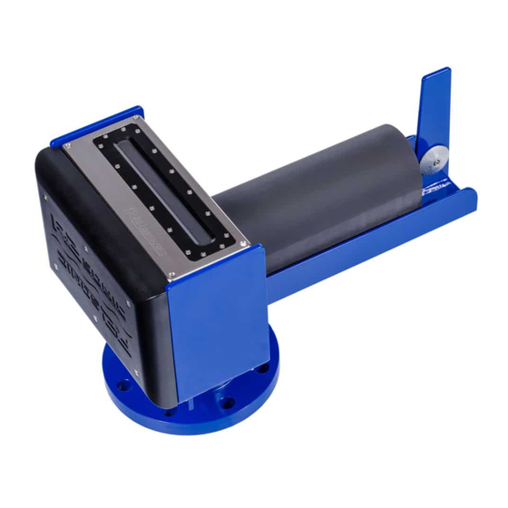
Page 49: Sonar Interface Module (Sim) Installation And Interfacing
SONAR INTERFACE MODULE (SIM) INSTALLATION and INTERFACING 4.1 Sonar Interface Module (SIM) Figure 35: Sonar Interface Module (SIM) The Sonar Interface Module is the communication centre for the Sonic MBES. The SIM receives commands from Sonic Control 2000 and passes the commands to the sonar head. The SIM also receives the PPS and timing information, which is transferred to the sonar head to accurately time stamp all bathymetry data in the sonar head. -
Page 50: Electrical And Interfacing
Pass through holes Figure 36: Removal of trim to expose securing holes 4.1.2 Electrical and Interfacing The SIM has four DB-9 male connectors on the front. The label, on the top, clearly shows all connections. Beginning on the left front, the connections are: GPS, Motion, Heading, and Sound Velocity. -
Page 51: Figure 37: Sim Interfacing Physical Connections
Figure 37: SIM Interfacing Physical Connections Figure 38: SIM Interfacing Guide (from the label on top of the SIM) NB. Again, at present, the SIM only takes in the PPS, NMEA Time message, sound velocity (at the sonar head) and motion data, but not heading information. Page 51 of 254 Version r012... -
Page 52: Figure 39: Sim Iec Mains Connection And Deck Lead Amphenol Ms Connector
Figure 39: SIM IEC mains connection and deck lead Amphenol MS connector Figure 40: Wet end connectors Non-Pressure Amphenol Pressure Rated Cable Rated Cable Function (14mm/0.55”) (10.2mm/0.40”) Number Wire Colour Number Wire Colour BI_DC+ Blue Blue BI_DC- Black paired with Blue Blue/White BI_DB- Green... -
Page 53: Table 11: As Of March 2021 Deck Lead Pin Assignment
As of March 2021, R2Sonic has standardised on one cable, R2Sonic 10288 (R2Sonic part number 37500005) Ø10.16mm (0.40”). Socket MCIL12F PT06J14-12P R2Sonic 10288 Wire Function Pin Number Pin Number Colour Data1+ White (paired with Blue) Data1- White/Blue Data2+ White (paired with Green) -
Page 54: Figure 41: Projector Cable Configuration
Figure 41: Projector cable configuration As of 17 March 2020, the projector cable has been standardised to part number 10228, with a diameter of 9.906mm (0.39 inches). The older model, in Figure 41, has a diameter of 10.16mm (0.40 inches). Page 54 of 254 Version r012... - Page 55 Figure 42: Projector cable as of 17 March 2022 Page 55 of 254 Version r012 Date 05-11-2022...
- Page 56 Page 56 of 254 Version r012 Date 05-11-2022 Part No. 96000001...
-
Page 57: Serial Communication
4.1.3 Serial Communication All serial interfacing is standard RS-232 protocol. Pin Data Receive Transmit Ground Table 12: DB-9M RS-232 Standard Protocol Pin Data Function Receive2 Secondary Serial Port Receive Primary Serial Input Transmit Primary Serial Output +12VDC +12VDC Power Ground Data and Power Common Not Connected +12VDC... -
Page 58: Motion Input
The standard time message is an NMEA sentence identified as $GPZDA and is expected to arrive after the PPS. The time message will also, usually, go to the data collection computer, so the ZDA message must either be split or output on two of the GPS receiver’s RS-232 ports. The $GPZDA and UTC message can be input to the SIM either via serial or Ethernet. - Page 59 start outputting sound velocity (Format: <sp> xxxx.xxx m/sec) as soon as power is applied, and it is in the water. The miniSVS cable is terminated with a female DB-9 RS-232 connector; this is attached to the male DB-9 RS-232 connector, on the SIM, marked SVP. The probe is powered through the SIM’s serial port 12VDC supply.
-
Page 60: Operation Of The Sonic Mbes Via Sonic Control
Sonic Control is supplied on a CD or as an attached file. There is no installation program, merely decompress the program to a folder in a root directory of the computer. Send the R2Sonic.exe to the desktop as a short cut (right-click on R2Sonic.exe and choose to Send to -> Desktop (create shortcut)). -
Page 61: Settings Menu
5.3 Settings Menu The Settings Menu provides access to the sonar setup and configuration. Each selection will be detailed. The order of the menu selections is not the order of setup. The initial sonar setup involves establishing communications between the sonar head, Sonic Control, and the SIM. Figure 46: Settings Menu 5.4 Network Setup All communication between the Sonic MBES and the SIM and data collection computer is via... -
Page 62: Discover Function
Sonar 1, in the Sonic Control 2000 Network settings. Use the Discover function to request the serial number information from all attached R2Sonic equipment. The Discover function will automatically transfer the serial numbers to the correct field. -
Page 63: Figure 48: Sonic Control Network Setup
5.4.2.1 Default Network Configuration Head IP: 10.0.0.86 BasePort: 65500 SIM: 10.0.0.99 BasePort: 65500 GUI: 10.0.1.102 BasePort: 65500 Bathy: 10.0.1.102 BasePort: 4000 (actual port 4000) Snippets: 10.0.1.102 BasePort: 4000 (actual port 4006) TruePix™: 10.0.1.102 BasePort: 4000 (actual port 4001) Water Column: 10.0.1.102 BasePort: 4000 (actual port 4005) INS: 10.0.0.44... -
Page 64: Configuring Network Communication
If the GUI IP number and subnet mask are set correctly, the Discover button will list the • R2Sonic devices attached to the network. If the GUI IP number and/or subnet mask is set wrong, Discover will not work, and the sonar head and SIM will not configure. - Page 65 Settings for Sonar 1: • Head IP: Any unique IP number within the network subnet. Head BasePort: Any number between 49152 and 65535. Preferred is 65500. SIM IP: Any unique IP number within the network subnet. SIM BasePort: Any number between 49152 and 65535. Preferred is 65500. GUI IP: Same IP number of the computer running the Sonic Control software.
-
Page 66: Sensor Setup (Serial And Ethernet Interfacing)
5.5 Sensor Setup (Serial and Ethernet Interfacing) The Sonar system receives various data on the SIM serial ports or via the Ethernet. Select Settings | Sensor setting to setup the communications parameters. Figure 53: Sensor serial communication settings 5.5.1 Ethernet Interfacing The system will accept the GPS time message, Motion, and SVP over Ethernet as well as the normal serial connection. -
Page 67: Gps
Figure 54: Sensor Ethernet communications settings 5.5.2 GPS The GPS input is for the ZDA time message ($GPZDA) or Trimble UTC message; other NMEA messages may be in the same string; it is not necessary to isolate the ZDA or UTC. In the GPS receiver’s operation manual, there will be an entry that will detail which edge of the PPS pulse is used for synchronisation;... -
Page 68: Trigger In / Trigger Out
5.5.6 Trigger in / Trigger out Used to receive or send synchronisation TTL pulses. Output goes high when transmitter pings, goes low after the receiver has collected data. Figure 55: Trigger In/Out Options 5.5.6.1 Trigger In The SIM Synch In input requires a TTL signal (0 to +5V) •... -
Page 69: Sonar Settings (Hotkey: F2)
5.6 Sonar Settings (Hotkey: F2) The Sonic MBES have many features that provide the user with the versatility to tailor the system to any survey project; many of these features can be controlled either through the Operation Settings or with the mouse cursor. Figure 56: Settings Menu Figure 57: Sonar Operation Settings window Page 69 of 254... -
Page 70: Frequency (Khz) 170 Khz - 450 Khz
5.6.1 Frequency (kHz) 170 kHz – 450 kHz The Sonic MBES operates on a user-selectable frequency, from 170 kHz to 450 kHz (standard with Type 1006 projectors; the Type 1004 projector is limited to 200 kHz to 400 kHz), in 10 kHz steps. The operating frequency can be changed on the fly;... -
Page 71: Ping Rate Limit
5.6.1.3 Sonic 2026 Low Frequency Option The Sonic 2026 has a low frequency option, which enables the Sonic 2026 to operate at 90 – 100 kHz for deeper area surveys. The Sonic 2026 uses a completely new projector that is larger than the standard Sonic 2024/2022 projector. -
Page 72: Figure 60: Sector Coverage
Figure 61: Sector coverage The Sector Coverage can also be controlled via the mouse cursor inside the wedge display. 5.6.3.1 Symmetric sector sizing Position the cursor on either of the straight sides of the wedge; the cursor will change to a double arrow, and the sector can be reduced or increased. -
Page 73: Sector Rotate
5.6.4 Sector Rotate The Sonic MBES has the capability to direct the selected sector to either port or starboard, allowing the user to map vertical features, or areas of interest, with a high concentration of soundings resulting from the compressed sector. First, change the sector coverage to the desired opening angle;... -
Page 74: Figure 63: Bottom Sampling Modes
A more technical way to look at this is the change over from equidistant to equiangular occurs when the outer beam grazing angle is 80° or greater. This is based on the below equation: (Swath Width / 2) + Head tilt + Sector rotate = grazing angle of the outermost beam Figure 64: Bottom Sampling Modes 5.6.6.1 Dual/Quad Mode The Dual/Quad bottom sampling modes can be used with both equiangular and equidistant... -
Page 75: Ultra High Density (Uhd™)
1024 soundings per ping. As opposed to producing pseudo beams by interpolating data to create the appearance of double the beams; R2Sonic searches across each beam footprint for additional soundings, using the extra-fine angular resolution that results from R2Sonic’s advanced signal processing to precisely locate each point. - Page 76 density and detail based on the acoustical properties of the bottom return acoustic signal = up to 1024 real bottom soundings. When operating in UHD mode, the data collection software storage files can become large with the additional soundings, and it is recommended to use the data collection software file splitting routines.
-
Page 77: Mission Mode
5.6.8 Mission Mode The versatility, built into the Sonic 2026/2024/2022 systems, is further enhanced with the ability to adapt the system to the nature of the survey task: normal survey, surveying a vertical feature, or the optional Forward Looking Sonar mode. -
Page 78: Figure 69: Enable Acoustic Image In The Wedge Display
Figure 70: Enable Acoustic Image in the wedge display 5.6.9.2 Forward Looking Sonar (Sonic 2024/2022-Requires Type 1004 projector) Forward looking mode can be in one of two configurations. FLS Wide uses the 20° projector within the Type 1004 projector. FLS Narrow uses the 1° standard projector. The wide mode, using the 20° projector, will have a lower source level, but is very good for near field use. -
Page 79: Figure 72: Stealth Mode Single Ping Button
Because of these advanced features, with the Sonic 2026 and Sonic 2020 FLS mode, there is an additional FLS option in the Settings menu that allows the user to set the Vertical Beamwidth and the degree of Vertical Steering. -
Page 80: Table 14: Sonic 2020/2026 Fls Vertical Beamwidth
Approximate Vertical Beamwidth in Degrees Setting Narrow Wide Default Table 14: Sonic 2020/2026 FLS Vertical Beamwidth As an example of the vertical steering: 400 kHz, the steering is ±10°. At 200 kHz, the steering is ± 20°. Page 80 of 254 Version... -
Page 81: Roll Stabilize And Pitch Stabilize
The R2Sonic roll stabilisation has been developed based on recommended methods from various data collection software companies. -
Page 82: Dual Head Mode (Also See Appendix Vii, Section 13.9)
5.6.11 Dual Head Mode (Also see Appendix VII, Section 13.9) The selections are Single Head, Simultaneous Ping or Alternating Ping. When the dual head mode is selected, a second wedge display will be available in Sonic Control 2000. When using dual heads, the sonar heads have to have exactly the same firmware installed. Use the Status display to verify that both heads have the same firmware;... -
Page 83: Figure 78: Load Settings Menu Selection
Figure 79: Load Settings menu selection The available settings files will be shown. There are three Factory Default initialisation files; two for single head: standard systems and I2NS systems and two for dual head: dual head – dual SIM or dual head –... -
Page 84: Truepix™, Snippets, Water Column Enable And Intensity Enable
Intensity Enable will output the bottom detection intensity value in the bathymetry packet; this is a standard feature. 5.6.12.1 TruePix™ Explained TruePix™ is a new backscatter imagery process developed by R2Sonic to combine the advantages of the traditional side scan record and Snippets while eliminating their respective disadvantages. Side scan records are: •... -
Page 85: Water Column Data Collection
(NIC) settings are very important to allow the computer to work with water column data collection. There are also Windows Registry settings that can be adjusted; please contact r2support@r2sonic.com for details on changing Registry settings. The NIC has to be Gigabit. It is very important to increase the Receive Buffer size, for the NIC, so that the NIC can handle the flow of the data. -
Page 86: Multimode
First introduced in 2016, the MultiSpectral mode provides a means to ping at different frequencies with each subsequent ping. R2Sonic has greatly enhanced the ability to tune the sonar on a ping to ping basis beyond just the frequency. The MultiSpectral mode is now a selection in a more enhanced MultiMode function. -
Page 87: Pipeline Mode
When loading a configuration, from the Presets, the user will be notified that the current settings are about to overwritten. Figure 89: Preset warning Under ‘Mission Mode’ there are preset options that can be used as a starting point or two Custom settings, which can be renamed by selecting the ‘Rename Mode’... - Page 88 sonar is put to 700kHz and the power adjusted for that frequency. If this is not done, it could be the Power setting may be too low for 700kHz, and the result will be noise instead of a good bottom return.
-
Page 89: Ocean Setting
5.8 Ocean Setting Figure 94: Ocean Characteristics Ocean Characteristics include Absorption and Spreading loss, which are the main components of the Time Variable Gain (TVG) computation, and manual Sound Velocity (for receive beam steering). 5.8.1 Absorption: 0 – 200 dB/km Absorption is influenced primarily by frequency and the chemical compounds of boric acid B(OH) and magnesium sulphate MgSO in the water column. -
Page 90: Time Variable Gain
NB. In very shallow water (2m or less) it may be more advantageous to use Fixed Gain. To put the system into Fixed Gain, enter zero (0) for both Spreading Loss and Absorption. For more detailed information on absorption and spreading loss, please refer to Appendix VI Basic Acoustic Theory. - Page 91 5.8.3.1 TVG Curve The TVG curve can be either shallow or steep, depending mostly on the Absorption value to define the shape of the curve. The Spreading Loss will determine the amplitude of the gain. Figure 95: TVG Curve Concept 5.8.3.2 Sound Velocity The speed of sound, at the receiver’s face, is required to do the receive beam steering, which is required for all flat array sonars.
- Page 92 WARNING The wrong sound velocity, at the sonar head, will cause erroneous data. There are currently no known post-processing tools to correct for this. If the sound velocity is wrong, the beam steering will be in error. If the sound velocity is greater than what it really is at the face of the receiver, the ranges will be shorter, and thus the bottom will curve up or ‘smile’.
-
Page 93: Installation Settings
Z offset of 0.119m for the Sonic 2024 and 2022 and 0.045m for the Sonic 2026 being the default. If the projector is not mounted in the same vertical relationship to the receive array, an offset can be entered here to compensate for that vertical offset. If the box is checked, Sonic Control will automatically choose the correct Projector Z offset for the system. -
Page 94: Status
5.10 Status Figure 98: Status Options The INS monitor is covered in Appendix I 5.10.1 System Status The Status report provides a detailed list of the current system parameters in both the sonar head and the SIM, including the current version of installed firmware and serial input messages. It is quite normal that the SIM messages, in the Head Status, differ slightly from the Serial port sensor data (in the SIM Status). -
Page 95: Saturation Monitor
The Saturation Monitor provides the user with the means of monitoring the sonar’s receiver signal level. The Saturation Monitor was developed by R2Sonic based on the work and input of Dr Jonathan Beaudoin (then with Centre for Coastal Mapping, University of New Hampshire). -
Page 96: Truepix™ Monitor
5.10.3 TruePix™ Monitor The TruePix monitor has been added to Sonic Control to provide users with a means to visualise the real-time imagery. It is important to note that with the addition of the TruePix monitor the manner in which TruePix are transmitted, from the head, has changed. TruePix data will only flow to the data collection software when Sonic Control is open. -
Page 97: Tools
5.11 Tools 5.11.1 Engineering This area is for engineering commands to be sent to either the head or SIM for either troubleshooting or system analysis. This area should not be used except by the direction of R2Sonic engineers. 5.11.2 Firmware Update... - Page 98 Figure 104: Select Tools; Firmware Update Figure 105: The Browse button will open the current GUI's directory Figure 106: Select correct update .bin file Figure 107: A batch file will automatically load the upgrade file Once the Update button is clicked on, a batch file will automatically run and download the .bin to the appropriate location.
- Page 99 Figure 108: The start of a firmware update. A series of dots represents the update progress. Figure 109: Firmware update completed. 5.11.2.1 Firewall and Virus Checker Issues A major problem can arise from having a firewall turned on (either Windows or a third party) and virus checkers.
-
Page 100: Snapshot And Reset Sector Rotate
associated keystrokes and LMB). The head will stop uplinking data (spinner stops) while the transmit firmware is being loaded. When the firmware is updated, the sonar will start pinging normally. 5.11.3 Snapshot and Reset Sector Rotate Both of these features can be activated using hotkeys. Snapshot will capture a single image of the GUI. -
Page 101: Remote Assistance
5.12.3 Remote Assistance R2Sonic support can assist in setting up the system or troubleshooting the system, remotely, by taking control of the customer’s computer. An internet connection is required. Figure 113: Remote Assistance When Remote Assistance is selected, a separate program will be launched that will allow R2Sonic Support to control the computer on which Sonic Control is installed remotely. -
Page 102: Display Settings
5.13 Display settings The user can customise the measurement units and colour scheme of Sonic Control’s main window. The Units dropdown allows for either metres or US Survey Feet. Whichever is selected will determine the labelling of the axes, the sound velocity and the nadir depth. NB. this is only for display purposes;... -
Page 103: Imagery
5.14 Imagery On the Imagery Tab, the user can select the imagery data (TruePix™ and Water Column) formats for logging. The maximum data size is shown to provide the user with an idea of what to expect when storing imagery data. The user can also select to apply the bathy gate settings to the TruePix™ data. Figure 118: Imagery Settings 5.14.1 TruePix™... -
Page 104: Robo Automatic Sonar Operation
5.15 ROBO Automatic Sonar Operation The sonar can be set up to automatically change Power, Pulse Width and Gain based on the Range setting and the percentage of receiver saturation. This feature is designed for ease of use, but the user must be aware that environmental factors play a very large part as to how successful the Robo settings control the sonar. -
Page 105: Robo Settings
5.15.1 Robo Settings Figure 121: Robo Settings 5.15.1.1 Auto Gain Adjustment The Robo feature uses the Range setting and the percentage of receiver saturation to determine when to change the Power, Pulse Width and Gain. The Range setting will determine the Power and Pulse Width. Receiver saturation percentage will set the Gain. -
Page 106: Main Operation Parameters
5.16 Main Operation Parameters The main operating parameters of the Sonic MBES are controlled by the buttons in the lower portion of the window. Figure 124: Operating parameter buttons To change a value, position the mouse cursor on the button then use the left mouse button to decrease the value and the right mouse button to increase the value. - Page 107 Straight legs of the wedge represent the Range setting; bottom detection dots must be above the corners. Figure 125: Range setting represented in the wedge display Figure 126: Graphical concept of the Wedge Display Page 107 of 254 Version r012 Date 05-11-2022...
-
Page 108: Rangetrac™ - Sonic Control Automatically Sets Correct Range
15µsec to 1115µsec. The Sonic 2026 pulse width range is from 15µsec to 2000µsec in normal mode. If the Extended Range option is installed in the Sonic 2026 and the sonar is operated at 90 kHz or 100 kHz, the minimum Pulse Width is 140µsec. The pulse width does not affect the pulse... -
Page 109: Gain: 1 - 45
amplitude, which is determined by the Power setting. The general guideline is to maintain as short a pulse width as possible to optimise the resolution, but not so short as to weaken the transmit pulse. It is suggested that 20µsec pulse width is considered the minimum to use. Generally, as the water gets deeper, the pulse width will have to be increased to get more ‘total’... - Page 110 Figure 130: Manual and GateTrac selections 5.16.6.1 Gates Manual The depth gates can also be changed using the mouse in the wedge display. Click and drag on either depth gate; the cursor will change to a double arrow , drag the gate to the new depth and release the mouse button.
- Page 111 If the soundings are visible, in the display then, when ‘GateTrac: Depth’ is enabled, the gates will automatically jump to the soundings, with the selected tolerance. The user can use the Gate Slope button to change the tilt of the gates, they will still automatically track the bottom, and the gate slope will not change from what the user has selected.
-
Page 112: Gui Rec(Ord)
This feature allows the user to record the entire GUI in x.264 format (extension is .mkv). Due to licensing, R2Sonic cannot redistribute the required executables for this format, and it is left to the customer to download ffmpeg.exe from http://ffmpeg.zeranoe.com/builds/. The ffmpeg.exe file needs to be in the Sonic Control directory or in the Windows search path. -
Page 113: Save Settings
released. The Range and Bearing information are along the bottom of the Sonic Control window. To remove, the Ruler use Ctrl + Double Click LMB. Figure 137: Ruler Function 5.19 Save Settings When Sonic Control is launched, it will always load the default settings configuration file located in the Sonic Control installation directory (CurrentSettings.ini). -
Page 114: Operating Sonic Control On A Second Computer
UDP ports. By doing Discover (in Settings | Network Settings), the system looks for all attached R2Sonic equipment, which will be identified by model and serial number. Once the serial number is discovered, it is used to assign an IP and UDP port to the sonar head and the SIM, after this is done, the IP and UDP ports can be changed. -
Page 115: Changing Back To One Computer
Figure 138: Change in GUI IP 5.20.2 Changing back to one computer 1) Open Sonic Control on the data collection computer. 2) Change the GUI address to 10.0.1.102 3) On the second computer, change the GUI IP address back to 10.0.1.102 and Apply. 4) Sonic Control, on the data collection computer now controls the system. - Page 116 Page 116 of 254 Version r012 Date 05-11-2022 Part No. 96000001...
-
Page 117: Sonic Mbes Theory Of Operation
6 SONIC MBES THEORY OF OPERATION The Sonic MBES transmits a shaped continuous wave pulse at the user-selected frequency. The transmit pulse is narrow in the alongtrack direction, but very wide in the across-track direction. The reflected acoustic energy is received via the Sonic MBES receivers; within the Receive Module the beams are formed, and the bottom detection process takes place. -
Page 118: Sonic Mbes Transmit (Normal Operation Mode)
The across-track angle is 160°; the along-track angle depends on frequency. The 450 kHz along-track pattern is 0.9° (0.5° for the Sonic 2026). The along-track lengthens out to 2° at 200 kHz. This is the Normal Operating Mode and not extended Vertical Mapping Mode. -
Page 119: Sonic Mbes Receive (Normal Operation Mode)
6.3 Sonic MBES Receive (Normal Operation Mode) The Projector is comprised of composite ceramics that convert electrical energy to acoustic energy. The composite ceramics, in the Receive Module, convert the reflected acoustic energy back to electrical energy. The small electrical voltage, generated by the ceramics, is amplified and then passed onto the receivers. - Page 120 Page 120 of 254 Version r012 Date 05-11-2022 Part No. 96000001...
-
Page 121: Sonic 2024/2022 Sonar Interface Module (Sim) Block Diagram
6.4 Sonic 2024/2022 Sonar Interface Module (SIM) Block Diagram RS-232 RS-232 Controller TTL - BNC Gigabit Ethernet Gigabit Switch Ethernet Power Supply 90 – 260 VAC To/From Sonar Head Sonar Connector Figure 142: Sonar Interface Module Block Diagram 6.4.1 Sonar Interface Module (SIM) Block Diagram 6.4.1.1 SIM Power Requirement The SIM operates within a voltage range of 90 to 260 VAC. - Page 122 Page 122 of 254 Version r012 Date 05-11-2022 Part No. 96000001...
-
Page 123: Appendix I: R2Sonic I2Ns Components And Operation
POS/MV; that information is found in the Applanix POS/MV manual. The information provided here covers the necessary setup of the R2Sonic I2NS components as relates to the R2Sonic SIM and Sonic Control. Where necessary, certain steps in the POSView software are detailed. -
Page 124: Type 82 Imu
7.1.1 Type 82 IMU In March 2021, R2Sonic updated the IMU portion of the I2NS. The updated IMU housing has Type82 etched along one side. The IMU offsets for the Type82 are the same horizontally, but the vertical offset is shifted upwards by 12.1mm. -
Page 125: Connection Diagram
7.2 Connection diagram When using the INS, there is no need to provide inputs for the motion or the time stamp, as those are provided internally through the SIM’s Gigabit switch. The only serial connection is the sound velocity probe that is on the sonar head. A PPS loop cable is required to go from the PPS out to the PPS in. -
Page 126: Installation
7.3 Installation 7.3.1 The IMU and GPS antennas The IMU (Inertial Measurement Unit) housing should be secured by 4 M8 (5/16” in Imperial units) screws. The IMU housing is depth rated to 15m. The IMU can be mounted close to or on the Multibeam transducer itself. -
Page 127: I2Ns Db9 Connections
7.3.3 I2NS DB9 Connections The I2NS has two serial communication ports and one dedicated to the internal GNSS board. The two com ports are standard DB9M serial connections that are set up in the POSView software. Both ports are bi-directional and can be configured to receive RTCM corrections or to output standard NMEA or binary serial data. -
Page 128: Setup In Sonic Control
2 minutes to power on; once the POS is fully booted, the IP can be set in the R2Sonic GUI. Once the POS is fully booted, the user has 5 minutes to change the IP address of the POS/MV. -
Page 129: Applanix Group 119 Specific To R2Sonic Simins
7.4.2 Applanix Group 119 specific to R2Sonic SIMINS Src: 10.0.0.44:65533 Dst: 10.255.255.255:5606 Applanix POS, Customer data Group 119 (MV customer defined group) Group start: $GRP Group ID: 119 (MV customer defined group) Byte count: 132 Time/Distance Fields: Time 1: 358370.467027857 (UTC seconds of the week) (Thu 03:32:50.467028 UTC) Time 2: 1091.53761465444 (POS seconds since power-on) (0.303205 hours) -
Page 130: Sensor Setup
Ethernet. The IP that the POS/MV stack sends data out is 10.0.0.44 and uses UDP port 5606, which is unique for R2Sonic requirements. The POS/MV Ethernet data, going to the data collection computer, is on the same IP (10.0.1.102), as the sonar data and uses the standard POS/MV UDP 5602. - Page 131 Page 131 of 254 Version r012 Date 05-11-2022...
-
Page 132: Measuring Imu Offsets
“Ref. to IMU Target” fields in POSView Be sure to check the box by “Enable Bare IMU”, as seen below. NOTE: Some older versions of POSView will not have this option. If not, please install the version preloaded on the R2Sonic CD that shipped with the Sonar. Page 132 of 254... - Page 133 Figure 159: POSView Lever Arm setup Use the View, when entering offsets, so that the correct sign is confirmed. This figure represents the physical installation, using the offsets that are seen in the above figure. Figure 160: View of installation with the entered offsets If the chosen Reference point is NOT the COG of the vessel, input the offsets from the ref to the COG in the “Ref.
-
Page 134: Imu Types
7.5.1 IMU Types Previous to March 2021, R2Sonic provided IMU Type 42 in the I2NS package; since March 2021, IMU Type 82 is the standard for the I2NS package. Horizontally, there is no change in the offsets between the types; vertically, the Type 82 IMU vertical reference is higher than the Type 42 IMU vertical reference by 12.1mm. -
Page 135: I2Ns Drawings
7.7 I2NS Drawings 7.7.1 I2NS Type 42 IMU Figure 163 Type 42: IMU Drawing Page 135 of 254 Version r012 Date 05-11-2022... -
Page 136: I2Ns Type 82 Imu
7.7.2 I2NS Type 82 IMU Figure 164: Type 82 IMU Offsets Page 136 of 254 Version r012 Date 05-11-2022 Part No. 96000001... -
Page 137: I2Ns Sonar Interface Module (Sim)
7.7.3 I2NS Sonar Interface Module (SIM) 280.00 mm [11.024 in] 48.92mm [1.926 in] UNLESS OTHERWISE SPECIFIED DESIGNED: P Steenstrup DIMENSIONS ARE IN MILLIMETERS DATE: 2013 06/10 DO NOT SCALE DRAWING SANTA BARBARA, CALIFORNIA SECTION A-A DWN: P Steenstrup TITLE: TOLERANCES INS SIM ENCLOSURE DATE: 2013 10/22... - Page 138 Page 138 of 254 Version r012 Date 05-11-2022 Part No. 96000001...
-
Page 139: Appendix Ii: Multibeam Survey Suite Components
APPENDIX II: Multibeam Survey Suite Components 8 APPENDIX II: Multibeam Survey Suite Components 8.1 Auxiliary Sensors and Components A multibeam survey system is comprised of more components than just the Sonic Multibeam Echosounder. These components are the auxiliary sensors, which are required to provide the necessary information for a multibeam survey. -
Page 140: Gps Calibration
during survey operations. If mounting the antenna on a vessel that has helicopter landing facilities, coordinate the placement of the antenna with the personnel in charge of helicopter operations. When the location for the antennae has been determined, the next step is determining how the coaxial cable, connecting the antenna and the receiver, is to be run. -
Page 141: Gyrocompass
Wrong geodetic transformations being applied to the WGS-84 position derived from GPS. • • Erroneous coordinates for the Differential reference station. 8.2.2.2 Position Accuracy Determination Method 2 This method is most easily accomplished during the gyrocompass calibration. The antenna remains mounted on the vessel. - Page 142 If possible, the vessel will be berthed alongside a quay or dock that has a survey • benchmark located nearby. • If a survey benchmark is not located close to the berth, then the surveyor will have to run a transit from the nearest, suitable, local survey benchmark to establish a point on the quay that has a well-defined position.
- Page 143 Figure 166: Gyrocompass Calibration method 1 Quayside Benchmarks have known geodetic positions. • • Measure Range and Bearing to reflectors on the vessel centre line. • Using Range and Bearing to reflectors, determine a geodetic position for reflectors. Calculate bearing from the stern reflector to bow reflector will give the true •...
- Page 144 8.3.1.2 Tape and Offset Method of Gyro Calibration This method relies on measuring the offset distance from a baseline on the quay, with a known azimuth, to a baseline that is established on the vessel. There are greater areas for error when using this method, particularly in establishing a baseline with known azimuth.
-
Page 145: Table 17: Gyro Calibration Method 2 Computation
The example, below, will illustrate the math involved. Figure 168: Gyro Calibration Method 2 example A to A' 1.0 metres B to B' 1.5 metres Side a 5.0 metres Side b 1.5 – 1.0 = 0.5 metres Angle b' Arctan 0.5/5.0 = 5.7° Ship Azimuth = 270°... -
Page 146: The Motion Sensor
8.4 The Motion Sensor The motion sensor is used to determine the attitude of the vessel in terms of pitch, roll and heave. Pitch is the movement of the bow going up and down. Roll is the movement of the port and starboard side going up and down. -
Page 147: Sound Velocity Probes
The motion sensor should be mounted on as level a platform as possible. After mounting the motion sensor, the actual 'mounting angles' should be measured. Some motion sensors contain internal programs that can measure the mounting angles. Some data collection software packages also include the capability to measure mounting angles. -
Page 148: Ctd Probes
The CTD and Time of Flight probes store the data internally. The data is downloaded to a computer after the probe is recovered. 8.5.1 CTD Probes The CTD probe type of sound velocity probe has instruments to measure the conductivity of the water, water temperature, and a pressure sensor to measure depth. -
Page 149: Time Of Flight Probe
8.5.2 Time of Flight Probe The Time of Flight probe incorporates a transducer that transmits an acoustic pulse that reflects back from a plate that it is at a very precise distance from the transducer. The two-way travel time is measured, divided by 2, and the sound velocity determined. The Time of Flight probe is usually considered more accurate for multibeam survey work. -
Page 150: The Sound Velocity Cast
and are used extensively by Navy and Defence forces for rapid determination of the sound velocity without stopping the vessel. 8.6 The sound velocity cast There are no set rules for when to take a measurement of the water column sound velocity. Common sense is a good guideline. - Page 151 5. Secure the bitter end of the downline to the vessel. 6. Request permission, from the bridge or helm, to deploy and await their OK to launch. a. Bridge or helm to ensure that the vessel is out of traffic. b.
- Page 152 Figure 172: Deploying a sound velocity probe via a winch or A-Frame The other major consideration, when deploying a probe in deeper water, is that the vessel must be stationary longer and will drift. If there is a large variation in depths, the depth where the probe went in, may not be the same depth when the probe reaches the bottom.
-
Page 153: Appendix Iii: Multibeam Surveying
APPENDIX III: Multibeam Surveying 9 APPENDIX III: Multibeam Surveying 9.1 Introduction Multibeam surveying affords the surveyor with many advantages, but it also requires more thought behind the survey itself. 9.2 Survey Design Multibeam surveying survey planning is very different than single beam survey planning. The main considerations are line spacing and line direction. -
Page 154: Line Run-In
slope is within the port or starboard swath coverage. There will be a poor definition of the slope covered by the nadir beams, as they act similar to a single beam echo sounder. In setting up the survey lines, if the lines were to run up and downslope, the spacing would have to vary between the start and the end of the lines, as the swath coverage would vary due to the change in water depth. -
Page 155: Daily Survey Log
The vessel record is meant to be a quick reference for general information that is required for multibeam surveying. Some of the information does not change from survey to survey and should go either in the front of the book or the back of the book. A section of pages can then be devoted to the information that does change from survey to survey or day to day. - Page 156 A copy of the survey log is sent along with the multibeam data to processing, and a copy is kept onboard the vessel. An example of the information on a smooth log: Sensor offsets • • Calibration offsets • Date •...
- Page 157 Figure 173: Rough log, kept during survey operations. (Log does not need to be neat, but must contain all pertinent information) Page 157 of 254 Version r012 Date 05-11-2022...
- Page 158 Figure 174: Smooth log; information copied from a real-time survey log...
-
Page 159: Appendix Iv: Offset Measurements
APPENDIX IV: Offset Measurements 10 APPENDIX IV: Offset Measurements 10.1 Lever Arm Measurement – Offsets Each component or sensor that produces information, unique to its position, will have a point that is considered the reference point of that sensor. The Sonic MBES, the motion sensor, and the GPS antenna will have a documented point from which to measure. -
Page 160: Measuring Offsets
Connector under Athwartship 240mm Figure 176: Sonic 2026/2024/2022 Acoustic Centre 10.3.2 Horizontal Measurement All measurements should be made with a metal tape measure. A cloth tape can stretch, it can also be knotted or kinked, unknown to the persons making the measurements. At a minimum, two people should be assigned to take the measurements;... -
Page 161: Vertical Measurement
either the reference point or the sensor is reached, the two people will reverse roles: the holder is now the reader, and the reader is the holder, the transverse is made back to the point of beginning, but not using the same path. If reference marks were made on the first leg, they should not be used on the second leg back. - Page 162 any temporary list the vessel is experiencing. On small survey vessels, a person leaning over the side, to take the draft measurement, can induce upwards, or exceeding a 10cm error in depth readings during survey operation. On some vessels, it is advisable to take draft readings during the survey or immediately after completion of the survey, as the draft will change that much.
-
Page 163: Appendix V: The Patch Test
APPENDIX V: The Patch Test 11 APPENDIX V: The Patch Test 11.1 Introduction The alignment of the Sonic MBES sonar head to the motion sensor and gyro is critical to the accuracy of the determined depths. It is not possible to install the sonar head in exact alignment with the motion sensor and gyro to the accuracy required (x.xx°). -
Page 164: Patch Test Criteria
11.3 Patch Test Criteria The patch test requires collecting sounding data over two distinct types of seafloor topography; a flat bottom is used for the roll computation whereas a steep slope or feature is used for the latency, pitch, and yaw data collection. Care must be taken that the sonar head covers the same area on both data collection runs, this may not be the same as vessel position, especially with an over-the-side mount or if the sonar head rotated. -
Page 165: Roll Test
11.3.2 Roll Test The data collection for roll has to be over a flat seafloor. One line is surveyed twice, in reciprocal directions and at survey speed. When the data, from the two data collections, are looked at in profile, there will be two seafloors sloped in opposite directions. -
Page 166: Pitch Test
11.3.3 Pitch Test The pitch data collection is over the same type of seafloor as the latency data collection, i.e. steep slope or feature on the seafloor. One line is surveyed, twice, in reciprocal directions at survey speed. It is very critical that the sonar head passes over the same exact part of the slope on each run. A profile of the data will show two different slopes, which represent the reciprocal data collections. -
Page 167: Yaw Test
11.3.4 Yaw Test The yaw data collection and subsequent solving for the yaw offset is usually the most difficult of the 4 tests that comprise a patch test. This is especially true if a slope is used for the yaw computation; a feature generally works much better. -
Page 168: Solving For The Patch Test
Position Error with a Heading Error of 1.0° Water Depth 200 metres 150 metres 100metre -100 50 metre 25 metres 10 metres Angle from Nadir Graph 4: Along-track position error caused by 1.0° error in yaw patch test error 11.4 Solving for the Patch Test Depending on the data collection software that is employed and how it solves for the patch test, there will be a distinct order that the tests will be solved for, but this does not influence the data collection for the patch test. -
Page 169: Basic Data Collection Criteria
11.6 Basic data collection criteria Patch test data collection does not have to be in any set order, but the order that the values are computed, in the data collection or processing software, will be in a distinct order. Normally, Latency is the first value that is computed, followed by Roll, Pitch and Yaw (or heading). -
Page 170: Water Depth
11.7.3 Water depth The deeper the water, the better the result. In shallow water, DGPS wobble creates more, relatively severe, position errors. A corollary to this is that the subtended angle is proportionally larger in shallow water, which can blur the definition of the object used, be it a feature or slope. -
Page 171: Improving The Patch Test And Patch Test Results
11.8 Improving the Patch Test and Patch Test results Section 11.7 described areas that should be addressed to improve the results of the patch test when collecting the data. Further improvement will come with the number of data collections and the manner in which the patch test is computed. 11.8.1 Need to collect sufficient data Too many times, surveyors will collect just a few lines of data for each test. -
Page 172: Individually Solving Values
11.8.2 Individually solving values No matter what the solving order may be, each value should be computed independently. All tests should be based on the mean of the previous test(s). It is important to understand why a certain solving order is used in all survey software. Each computation is based on the previous test result. -
Page 173: Appendix Vi: Basic Acoustic Theory
APPENDIX VI: Basic Acoustic Theory Figure 183: In 1822 Daniel Colloden measuring velocity in Lake Geneva (Daniel Colloden used an underwater bell to calculate the speed of sound underwater in Lake Geneva, Switzerland at 1435 m/Sec, which is very close to recent measurements) 12 APPENDIX VI: Basic Acoustic Theory 12.1 Introduction With multibeam, as with any echosounder, the main concern is sound in water. - Page 174 Figure 184: Concept of refraction due to different sound velocities in the water column The velocity of sound in water varies both horizontally and vertically. It cannot be assumed that the velocity of sound in the water column remains constant over large areas or throughout the day in a more local area.
-
Page 175: Salinity
12.2.1 Salinity Generally, salinity ranges from 32 – 38 parts per thousand (ppt) in ocean water. A change in salinity will create density changes, which affect the velocity of sound. As a general rule, a change in salinity of only 1 ppt can cause a sound velocity change of 1.4m/sec. There are many influences on the salinity concentration in seawater. -
Page 176: Transmission Losses
12.3 Transmission Losses The transmission of an acoustic pulse is generally called a ‘ping’. When the projector sends out the acoustic pulse, many factors operate on that pulse as it moves through the water column to the bottom and also on its return upward. The major influence of the water column sound velocity characteristics was detailed above;... -
Page 177: Absorption
Figure 188: Concept of Cylindrical Spreading 12.3.2 Absorption Absorption is frequency dependent and refers to the conversion of acoustic energy to heat when it strikes chemically distinct molecules in the water column. Magnesium Sulphate MgSO predominates, with Boric Acid B(OH) playing a major part at lower frequencies. -
Page 178: Table 18: Absorption Values For Seawater And Freshwater At 400 Khz And 200 Khz
The below table and charts illustrate how frequency, water temperature, and salinity affect absorption Seawater Absorption Values: Salinity = 35ppt, pH=8 dB/km 400kHz 200kHz Temp (C) 5° 10° 15° 20° 25° 5° 10° 15° 20° 25° Depth (m) 97 100 111 130 154 96 100 110 128 153 99 110 128 152 99 109 127 151... -
Page 179: Graph 5: Seawater Absorption (Salinity 35Ppt)
Frequency and Temperature Influence on Seawater Absorption 400kHz 200kHz Mean values for water depths from 50 metres to 300 metres (400 metres for 200 kHz) 5° 10° 15° 20° 25° Degrees Celsuis Graph 5: Seawater Absorption (Salinity 35ppt) Frequency and Temperature Influence on Freshwater Absorption 400 kHz 200 kHz... -
Page 180: Sound Absorption Graphs At Select Frequencies
12.3.3 Sound Absorption Graphs at Select Frequencies Sound Absorption (Francois-Garrison) 40 ppt 5 ppt Fresh Water Frequency = 200 kHz Water Temperature (°C) Depth = 20m Graph 7: 200 kHz Sound Absorption Sound Absorption (Francois-Garrison) 5 ppt Fresh Water Frequency = 300 kHz Water Temperature (°C) Depth = 20m Graph 8: 300 kHz Sound Absorption... -
Page 181: Graph 9: 400 Khz Sound Absorption
Sound Absorption (Francois-Garrison) 5 ppt Fresh Water Frequency = 400 kHz Water Temperature (°C) Depth = 20m Graph 9: 400 kHz Sound Absorption Sound Absorption (Francois-Garrison) 5 ppt Fresh Water Frequency = 700 kHz Depth = 20m Water Temperature (°C) Graph 10: 700 kHz Sound Absorption Page 181 of 254 Version... - Page 182 Page 182 of 254 Version r012 Date 05-11-2022 Part No. 96000001...
-
Page 183: Table 19: Operating Frequency - Water Temperature - Absorption (@50M)
Seawater Absorption dB/km Freq. 10°C 15°C 20°C 25°C 30°C Table 19: Operating Frequency - water temperature – absorption (@50m) At 700 kHz, there is an absorption dip, in this temperature range Page 183 of 254 Version r012 Date 05-11-2022... -
Page 184: Reverberation And Scattering
12.3.4 Reverberation and Scattering The sea is not homogenous in nature. Everything from suspended dust particles to fish, from the sea surface to the seafloor, will scatter, that is reradiate the acoustic energy. All of the effects of individual scattering can be termed reverberation. The effect of reverberation is to lessen the acoustic energy, and this leads to transmission losses. -
Page 185: Appendix Vii: Sonic Mbes Mounting: Sub-Surface (Rov/Auv)
Appendix VII ROV and AUV Installation 13 APPENDIX VII: Sonic MBES Mounting: Sub-Surface (ROV/AUV) 13.1 Installation Considerations A 1000BASE-T link (best time sync accuracy) is preferred; however, with bathymetry only • information, 100BASE-T will work. 10BASE-T will also work but is not recommended. Bathy data requires 2 Mb/s data rate at a maximum ping rate of 60 pings/sec. -
Page 186: Ethernet Wiring Considerations
13.1.1 Ethernet wiring considerations The sonar head and SIM use Gigabit Ethernet ports. There are rules regarding the number of twisted pairs, between different Ethernet ports, these rules are: Gigabit to Gigabit • Need all four pairs. If only two pairs used, in an attempt to force the ports to 100BASE-T, the ports will not negotiate, and the result will be no connection. -
Page 187: Rov Installation Examples
13.3 ROV Installation Examples Figure 189: Single Head ROV Installation scheme A Figure 190: Single Head ROV Installation scheme B (Preferred) Page 187 of 254 Version r012 Date 05-11-2022... - Page 188 Figure 191: Dual Head ROV Installation scheme A Figure 192: Dual Head ROV Installation scheme B (Preferred) Page 188 of 254 Version r012 Date 05-11-2022 Part No. 96000001...
-
Page 189: Power Requirements
In an ROV or AUV installation, the sonar head and SIM Controller board require 48VDC, supplied by the vehicle power system. During the receive cycle, the power required is 55 watts for the 2026, 50W for the 2024, and 35 watts for the 2022. The peak current draw occurs just after transmission when the capacitor bank recharges. - Page 190 Figure 193: Sonic 2024 power supply current waveform. Peak current is 1.770A at 48V. Sonar settings: pulse width = 100us, Tx Power = 221dB, Freq = 400 kHz. Figure 194: Inrush current to 2024 head during power-up, 20 ms window. Page 190 of 254 Version r012...
-
Page 191: Common Mode Noise Rejection
Figure 195: Inrush current to the 2024 head during power-up, 1-second window. 13.4.1 Common mode noise rejection Common mode noise on the 48VDC power line to the sonar head should be minimized. The SIM Controller board has a common mode choke on the power line to the sonar head. If sonar head power is not supplied by the SIM Controller board, install a common mode choke on the sonar head 48VDC power line. -
Page 192: Sim Power Connections
13.4.2 SIM Power connections Figure 197: SIM Controller Board The mating connector for J4: Molex 43645-0800 (8-way Micro-FIT 3.0) Molex 43030-0009 (socket contacts) Molex 63819-0000 or 63811-2800 (crimping tool for socket contacts) The mating connector for J6: Amp 2-111623-4 Any 2mm 2x20 header connector may be used for this part. 1mm pitch ribbon cable is also required Figure 198: J6 Connector on SIM Controller board Page 192 of 254... -
Page 193: Sim Installation - Rov
13.5 SIM Installation – ROV The SIM can be installed on either the top-side or in the vehicle. There are advantages to both methods which depend on the multiplexer capabilities. For SIM installation in the vehicle, the SIM Controller board may be removed from the SIM or supplied as an additional item. The SIM controller board uses a PC/104 size format but does not use the PC/104 bus. -
Page 194: Sim Installation - Auv
13.6 SIM Installation – AUV The circuit boards, inside the SIM, can be supplied separately as a SIM Stack (see below images). The three boards use a PC/104 size format, but do not use the PC/104 bus. The three boards are the I/O board where the customer connects time, motion and sound velocity sensors;... -
Page 195: Version Rev Date
13.7 SIM Board Physical Installation 1. Power limits: 48VDC, 50 watts average, 100 watts peak. 2. 36VDC is absolute minimum working voltage; 52VDC is an absolute maximum working voltage 3. All boards are static sensitive. People handling the boards should be properly grounded. 4. -
Page 196: Sim Board Dimensional Information
13.8.1 SIM Board Dimensional Information Dimensions are given are in inches [millimetres] Figure 205: SIM Controller Board installation dimensions Figure 206: SIM Stack Outline Page 196 of 254 Version r012 Date 05-11-2022 Part No. 96000001... -
Page 197: Sim Board Images
13.8.2 SIM Board Images Figure 207: Assembled SIM Boards Figure 208: SIM Boards height Page 197 of 254 Version r012 Date 05-11-2022... - Page 198 Page 198 of 254 Version r012 Date 05-11-2022 Part No. 96000001...
-
Page 199: Dual Sonar Head
13.9 Dual Sonar Head 13.9.1 Dual Head Installation The R2Sonic family of multibeams can be installed in a dual head configuration, either pointing inwards or directed outwardly, depending on the customer’s survey task. In dual head mode, the individual sonar heads can either ping simultaneously (with frequency offset) or alternate pings (same frequency). - Page 200 13.9.2.2 Dual Head – Same Frequency – Alternating ping To operate the dual sonar heads on the same frequency, it is necessary to coordinate the transmit and receive periods, so there is no interference. Operating in the ‘Ping-Pong’ mode will halve the ping rate for each head, but the user gains identical acoustic resolution (such as backscatter) for both sonar heads.
-
Page 201: Appendix Viii: R2Sonic Control Commands
Appendix VIII Sonic Control Commands 14 APPENDIX VIII: R2Sonic Control Commands 14.1 Introduction This describes the commands sent from the user interface to the sonar head and SIM. Head firmware version 14-Mar-2011 and SIM firmware version 08-Apr-2010 utilize the commands in this document. -
Page 202: Head Commands, Binary Format
FRQ0 170000 to 450000 Frequency FRQ1 700000 for UHR FRQ1 – FRQ4 are used for MultiMode selections. FRQ2 90000, 100000 for 2026 LF Option FRQ3 FRQ4 GAN0 1 to 45 Rcvr gain. gain in dB = setting * 2 GAN1 GAN1 –... - Page 203 Cmd Format Units Values Description PRL0 0.1 to 60 Ping rate limit user-value PRO0 0 = projector forward Projector orientation 1 = projector aft PROJ 0 = none Projector type selector 1 = narrow (1°) 2 = wide (20°) (only in FLS mode) PRU0 0 = off Ping rate limit user-enable...
- Page 204 Along-track apodization and size of tx array. 0xn0 1 = Kaiser weighting (≈ -2.3 dB SL) command only works on 2020 and 2026. 0xn0: 0xn0 = number of tx staves where proportional to number of staves, see list in manual.
-
Page 205: Sim Commands, Binary Format
14.4 SIM Commands, Binary Format Format Units Values Description BDG0 standard baud rates GPS baud 300 to 115200 BDH0 standard baud rates Heading baud 300 to 115200 BDM0 standard baud rates Motion baud 300 to 115200 BDS0 standard baud rates SVP baud 300 to 115200 DBG0... -
Page 206: Gui Commands, Binary Format
10° to 160° Sector width SPR0 0 to 60 Spreading loss typically 20 TXL0 seconds Transmitter pulse length 0 to 1115µs for 2020, 2022 and 2024 0,140µs to 2000µs for 2026 Page 206 of 254 Version r012 Date 05-11-2022 Part No. 96000001... -
Page 207: Gui Command Line Switches
Format Units Values Description TXP0 dB/1µPa 0, 191 to 221 Transmitter power WCR0 0 = off Water column enable, head 1. 1 = on Equivalent to setting the water column check box in the GUI WCR1 Water column enable, head 2. Equivalent to setting the water column check box in the GUI Note the commands which set angle values are in degrees. -
Page 208: Command Examples Sent To The Sonar Head And Sim
14.6 Command Examples Sent to the Sonar Head and SIM Example of commands sent to the sonar head every two seconds. Columns after the command are hex, integer, and floating point representations of the data sent for each command PacketName: CMD0 Command: ABS0 0x42a00000 1117782016 80.000000 Command: SPR0 0x41a00000 1101004800... - Page 209 Command: SBS0 0x00000001 0.000000 Command: SPO0 0x00000001 0.000000 Command: STM0 0x00000002 0.000000 Example of UDP/IP Ethernet packet of commands sent to the sonar head. First 42 characters are Ethernet header information. Characters after 29h are commands 0000 00 50 c2 90 44 a3 00 1b 21 40 04 84 08 00 45 00 .P..D...!@..E. 0010 01 48 09 8b 40 00 80 11 00 00 0a 00 01 66 0a 00 .H..@..f..
- Page 210 Page 210 of 254 Version r012 Date 05-11-2022 Part No. 96000001...
-
Page 211: Appendix Ix: R2Sonic Uplink Data Formats
Appendix IX: R2Sonic Data Format 15 APPENDIX IX: R2Sonic Uplink Data Formats 15.1 Introduction This describes the data formats sent from the sonar head and SIM. Unless noted, the data packets are sent from the sonar head. The formats are given in pseudo C. -
Page 212: Ethernet Data Rates
15.5 Ethernet Data Rates Bathymetry: ≈ 800 kb/s max (bathy data is sent twice, to GUI and data acquisition computer) TruePix: ≈ 5.5 Mb/s (magnitude + angle) max ≈ 3.5 Mb/s (magnitude) max Water Column: ≈ 560 Mb/s (magnitude + phase) max ≈280 Mb/s (magnitude) max Snippets: ≈... -
Page 213: Bathymetry Packet Format
// [radians] u16 H0_2026ProjTemp; // [hundredths of a degree Kelvin] 2026 projector temperature (divide value by 100, subtract 273.15 to get °C) s16 H0_VTX+Offset; // [hundredths of a dB] transmit voltage offset at time of ping (divide value by 100 to get dB) f32 H0_RxBandwidth;... - Page 214 // section R0: 16-bit bathy point ranges u16 R0_SectionName; // 'R0' u16 R0_SectionSize; // [bytes] size of this entire section f32 R0_ScalingFactor; u16 R0_Range[H0_Points]; // [seconds two-way] = R0_Range * R0_ScalingFactor u16 R0_unused[H0_Points & 1]; // ensure 32-bit section size // section A0: bathy point angles, equally-spaced (present only during "equi-angle"...
- Page 215 // section G0: simple straight-line depth gates u16 G0_SectionName; // 'G0' u16 G0_SectionSize; // [bytes] size of this entire section f32 G0_DepthGateMin; // [seconds two-way] f32 G0_DepthGateMax; // [seconds two-way] f32 G0_DepthGateSlope; // [radians] // section G1: 8-bit gate positions, arbitrary paths (present only during "verbose" gate description mode) u16 G1_SectionName;...
-
Page 216: Snippet Format
// [radians] u16 H0_2026ProjTemp; // [hundredths of a degree Kelvin] 2026 projector temperature (divide value by 100, subtract 273.15 to get °C) s16 H0_VTX+Offset; // [hundredths of a dB] transmit voltage offset at time of ping (divide value by 100 to get dB) f32 H0_RxBandwidth;... - Page 217 // section S1: 16-bit snippet data (for network efficiency packet may contain several of these sections) (supports snippets up to 32K samples by fragmenting // at the IP level rather than by the application like 81xx) u16 S1_SectionName; // 'S1' u16 S1_SectionSize;...
-
Page 218: Water Column (Wc) Data Format
15.8 Water Column (WC) Data Format // *** BEGIN PACKET: WATER COLUMN (WC) DATA FORMAT 0 *** // The water column data contains real-time beamformer 16-bit magnitude data // (beam amplitude) and optional 16-bit split-array phase data (intra-beam // direction). The maximum data rate is about 70 megabytes per second (assuming // 256 beams, 68.4 kHz sample rate, and phase data enabled). - Page 219 // section H0: header (only one per ping) u16 H0_SectionName; // 'H0' u16 H0_SectionSize; // [bytes] size of this entire section u8 H0_ModelNumber[12]; // example "2024", unused chars are nulls u8 H0_SerialNumber[12]; // example "100017", unused chars are nulls u32 H0_TimeSeconds; // [seconds] ping time relative to 0000 hours 1-Jan-1970, integer part u32 H0_TimeNanoseconds;...
- Page 220 f32 M1_ScalingFactor; // reserved for future use u32 M1_TotalSamples; // range samples in entire ping, sample rate is H0_RxSampleRate u32 M1_FirstSample; // first sample of this section u16 M1_Samples; // number of samples in this section u16 M1_TotalBeams; // beams (always a multiple of 2) (typically columns in your memory buffer) u16 M1_FirstBeam;...
-
Page 221: Acoustic Image (Ai) Data Format
15.9 Acoustic Image (AI) Data Format // *** BEGIN PACKET: ACOUSTIC IMAGE (AI) DATA FORMAT 0 *** // The acoustic image data contains real-time beamformer 8-bit magnitude data // (beam amplitude) that has been scaled to 8-bits by a user-selected // brightness value, and compressed in range by an adjustable amount to // reduce network bandwidth and processing. - Page 222 // [radians] u16 H0_2026ProjTemp; // [hundredths of a degree Kelvin] 2026 projector temperature (divide value by 100, subtract 273.15 to get °C) s16 H0_VTX+Offset; // [hundredths of a dB] transmit voltage offset at time of ping (divide value by 100 to get dB) f32 H0_RxBandwidth;...
-
Page 223: Truepix™ Data Format
// [radians] u16 H0_2026ProjTemp; // [hundredths of a degree Kelvin] 2026 projector temperature (divide value by 100, subtract 273.15 to get °C) s16 H0_VTX+Offset; // [hundredths of a dB] transmit voltage offset at time of ping (divide value by 100 to get dB) f32 H0_RxBandwidth;... -
Page 224: Head Status Format
f32 H0_RxAbsorption; // [dB per kilometer] f32 H0_RxMountTilt; // [radians] u32 H0_RxMiscInfo; // reserved for future use u32 H0_reserved; // reserved for future use f32 H0_MoreInfo_0; // roll [radians] f32 H0_MoreInfo_1 //Z-offset, proj [metres] f32 H0_MoreInfo_2; //Y-offset, proj [metres] f32 H0_MoreInfo_3; //X-offset, proj [metres] f32 H0_MoreInfo_4;... - Page 225 // Each section name consists of 4 characters. The fourth character // indicates the number of 32-bit words following each section name. // The forth character can be 1-9, A-Z; allowing up to 35 32-bit words. // The number of words in each section may change at a later date. Be // sure your program can parse the number of words.
- Page 226 // water_column[3:3] 0=off, 1=on // ultra-high resolution[4:4] 0=off, 1=on // water column rx chan [5:5] 0=off, 1=on // 2026 low freq option [6:6] 0=off, 1=90 & 100kHz enabled, 2026 only // section CFG8: configuration parameters u32 CFG8 SectionName; // 'CFG8' f32 pdepth_cutout;...
- Page 227 u32 ethernet.speed; // [megabits/sec] link connect speed u32 erxpackets; // [counts] ethernet receive packets u32 etxpackets; // [counts] ethernet transmit packets u32 erxoverflows; // [counts] ethernet receive buffer overflows u8 mac.addr[8] // mac address, use last 6 bytes, first 2 bytes are not used // section TIM2;...
-
Page 228: Sim Status Data Format
15.12 SIM Status Data Format // *** BEGIN PACKET: SIM STATUS DATA FORMAT 0 *** // SIM Status data reports misc info from the SIM box. This data is // useful for troubleshooting. Data is sent to gui baseport+2. // Each section name consists of 4 characters. The fourth character // indicates the number of 32-bit words following each section name. - Page 229 // section LED1: SIM front panel LED status u32 LED1_SectionName; // 'LED1' u32 led_status; // [00=off 01=undef 10=bad 11=good] flags for status LEDs // gps[1:0] // motion[3:2] // heading[5:4], not implemented // svp[7:6] // alt-gps[9:8], not implemented // alt-motion[11:10], not implemented // alt-heading[13:12], not implemented // alt-svp[15:14], not implemented // pps[17:16]...
-
Page 230: Device Status Format
IP address. The ConfigID received from the sonar head and SIM should be compared with the ConfigID number sent to the sonar head and SIM during IP configuration. If there is a mismatch, the control program should send IP configuration data to the sonar head and/or SIM to correct the issue. struct R2DS // R2Sonic Device Status u32 PacketName; // 'R2DS' C structure of Device Status packet u32 SerialNumber[3];... -
Page 231: Data Playback Using Bit-Twist
Using Wireshark, uplink data from the sonar head can be captured, filtered, and saved. Bit Twist, a console application, allows you to playback data. R2Sonic can supply sample Ethernet captures of the sonar head uplink data. You may need to edit the destination MAC and IP addresses of the captured data with Bit-Twiste, a console application. -
Page 232: Editing Data
Figure 213: Wireshark Capture Options This will reduce the processing load on Wireshark significantly. •After capture, filter the data so only the desired sonar head data is displayed. A filter expression like “not(icmp.type == 3 or ip.src == 10.0.1.102)” can be used to filter data coming from the data acquisition computer. •Save using Save As, data type as “Wireshark/tcpdump/…- libpcap (*.pcap,*.cap)”... -
Page 233: Data Playback
Newer Ethernet playback utilities are better than bittwist. Ask support about a modified version of Playcap.exe (Open Source program modified for looping) and Wireplay.exe (R2Sonic program that can play back pcap files at full speed and you don't need to edit pcap files with bitttwiste). - Page 234 Page 234 of 254 Version r012 Date 05-11-2022 Part No. 96000001...
-
Page 235: Appendix X: Drawings
Figure 223: SIM Box Drawing ........................................246 Figure 224: SIM Stack Outline ........................................247 Figure 225: R2Sonic Deck lead minimum connector passage dimensions ..........................248 Figure 226: Locking Ring type Deck Lead ..................................... 249 Figure 227: I2NS Type 42 IMU Dimensions ....................................250 Figure 228: I2NS Type 82 IMU offsets ...................................... - Page 236 Measurements valid for all styles of projectors including older style projectors without the clamp bosses. Figure 214: Sonic 2024/2022 Projector Page 236 of 254 Version r012 Date 05-11-2022 Part No. 96000001...
- Page 237 Figure 215: Sonic 2026 Projector Page 237 of 254 Version r012 Date 05-11-2022...
- Page 238 Cable tie down removed with new receivers with cable clamps Figure 216: Sonic 2024/2026 Receive Module Page 238 of 254 Version r012 Date 05-11-2022 Part No. 96000001...
- Page 239 Cable tie down removed with new receivers with cable clamps Figure 217: Receiver outline with penetrator Page 239 of 254 Version r012 Date 05-11-2022...
- Page 240 Cable tie down removed with new receivers Figure 218: Sonic 2022 Receive Module Page 240 of 254 Version r012 Date 05-11-2022 Part No. 96000001...
- Page 241 Figure 219: Sonic 2022 Receiver / Projector horizontal offset Page 241 of 254 Version r012 Date 05-11-2022...
- Page 242 Figure 220: Sonic 2024 Mounting Bracket Drawing Page 242 of 254 Version r012 Date 05-11-2022 Part No. 96000001...
- Page 243 Figure 221: Sonic 2022 Mounting Bracket Drawing Page 243 of 254 Version r012 Date 05-11-2022...
- Page 244 Figure 222: Sonic 2026 Mounting Bracket Drawing Page 244 of 254 Version r012 Date 05-11-2022 Part No. 96000001...
- Page 245 Figure 223: Sonic 2024/2022 Mounting Bracket Flange Page 245 of 254 Version r012 Date 05-11-2022...
- Page 246 Figure 224: SIM Box Drawing Page 246 of 254 Version r012 Date 05-11-2022 Part No. 96000001...
- Page 247 Figure 225: SIM Stack Outline Page 247 of 254 Version r012 Date 05-11-2022...
- Page 248 Figure 226: R2Sonic Deck lead minimum connector passage dimensions Page 248 of 254 Version r012 Date 05-11-2022 Part No. 96000001...
- Page 249 Figure 227: Locking Ring type Deck Lead Page 249 of 254 Version r012 Date 05-11-2022...
- Page 250 Figure 228: I2NS Type 42 IMU Dimensions Page 250 of 254 Version r012 Date 05-11-2022 Part No. 96000001...
- Page 251 Figure 229: I2NS Type 82 IMU offsets Page 251 of 254 Version r012 Date 05-11-2022...
- Page 252 Figure 230: I2NS IMU Cable Page 252 of 254 Version r012 Date 05-11-2022 Part No. 96000001...
- Page 253 Figure 231: I2NS SIM Dimensions Page 253 of 254 Version r012 Date 05-11-2022...
- Page 254 Figure 232: Dual Head Mount Offsets Page 254 of 254 Version r012 Date 05-11-2022 Part No. 96000001...
Need help?
Do you have a question about the 2026 and is the answer not in the manual?
Questions and answers
Hello can you told me about price of the equipment